Do you have a question about the GE DVM1950 and is the answer not in the manual?
Detailed precautions for safe servicing to prevent microwave energy exposure.
Instructions for safe operation and precautions to prevent microwave energy exposure.
Explanation of the model number's components and their meaning.
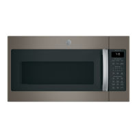
Overview of the microwave oven's key features and advantages for users.
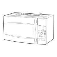
Description of physical components and their functions, including door, latches, and window.
Details on the energy-saving feature that reduces standby power consumption.
Explanation of buttons for various cooking modes like time, defrost, and settings.
Details on special features like Steam, MyPlate.gov, and Family Snacks for easy meal preparation.
Explanation of buttons for cooking, defrost, settings, timer, and express cook functions.
Details on features like popcorn, reheat, family snacks, soften, melt, and MyPlate.gov.
Explanation of buttons for cooking, defrost, settings, timer, power level, and express cook.
Details on features like popcorn, beverage, potato, reheat, family snacks, melt, and steam.
How to use the MyPlate.gov feature for healthy meal choices using sensor cooking.
Guide to food groups, types, and servings for the MyPlate.gov feature.
Diagram identifying key components visible from the front of the microwave.
Identifies components after the control panel assembly has been removed from the front.
Diagram showing component locations when viewed from the right side of the oven.
Diagram showing component locations when viewed from the top right side of the oven.
Illustration of the smart board with labels for its various connectors and components.
Illustration of the display board, showing its connection to the smart board.
Step-by-step instructions for safely removing the microwave oven from its installation.
Instructions for removing and reinstalling the grille assembly on the microwave oven.
Detailed steps and screw locations for removing the microwave oven's outer casing.
Procedure for removing the microwave oven door assembly, including hinge clips.
Information on the interior light bulb and its replacement procedure.
Explanation of the power saver feature, its operation, and recommendations for use.
Description and removal/reinstallation instructions for the stirrer assembly.
Information on the line and high voltage fuses, their locations, and removal.
Explanation of the noise filter's function and how to check its resistance values.
Instructions for removing the vent blower assembly from the microwave oven.
Step-by-step guide to removing the control panel assembly and its connectors.
Details on the door sensing and primary interlock switches and their function.
Explanation of the monitor switch's operation and its role in oven safety.
Instructions for removing the smart board, including connector and screw locations.
Steps for removing the display board from the control board frame.
Information about the bottom TCO, its function, and removal process.
Instructions for removing the turntable coupling from the motor shaft.
Information about the surface lamps and how to replace them.
Steps for removing the turntable motor from the microwave oven cabinet.
Procedure for removing the magnetron thermal cut out (TCO).
Warning and steps for removing the magnetron, including capacitor discharge.
Instructions for removing the vent fan motor capacitor.
Steps for removing the cavity thermal cut out (TCO) device.
Instructions for removing the vent thermal cut out (TCO).
Detailed steps for removing the cooling fan motor assembly.
Procedure for removing the high voltage capacitor and diode.
Steps for removing the high voltage transformer, including warnings.
Instructions for entering and exiting Demo Mode on 2.1 Series models.
Instructions for entering and exiting Demo Mode on 1.9 Series models.
A flowchart to diagnose and resolve common operational issues with the microwave oven.
Procedure for testing microwave leakage and ensuring compliance with safety standards.
List of displayed error messages and their corresponding descriptions.
Guide for testing the functionality of control panel buttons and display.
Technical specifications and connector pinouts for the smart board.
Steps to test the continuity of the door interlock switches.
Procedure to test the monitor switch and its circuit operation.
Explanation of the sensor cooking function and the gas sensor's role.
Steps to perform sensor cooking and quick diagnostic tests on the sensor.
Procedure for verifying key panel pad continuity using a ribbon cable diagram.
Electrical schematic diagram for the PVM2170 model showing component connections.
Detailed wiring diagram for the PVM2170 model, including harness and parts leads.
Electrical schematic for multiple models, detailing component interconnections.
Wiring diagram for multiple models, showing harness and parts lead connections.
Explanation of the half-wave voltage doubler circuit's operation and components.
Details on the warranty coverage, limitations, and exclusions for GE microwave ovens.
| Brand | GE |
|---|---|
| Model | DVM1950 |
| Category | Microwave Oven |
| Language | English |