GE Multilin F60 Feeder Protection System 5-65
5 SETTINGS 5.2 PRODUCT SETUP
5
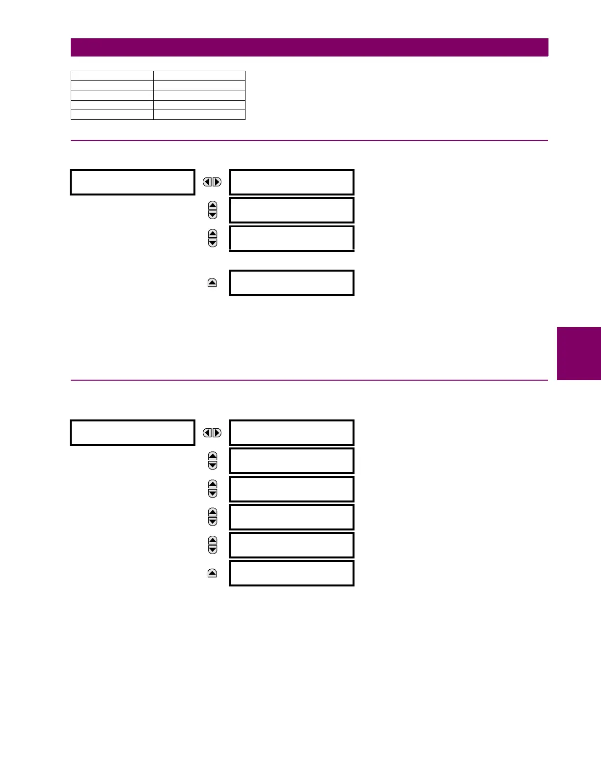
5.2.5 MODBUS USER MAP
PATH: SETTINGS PRODUCT SETUP MODBUS USER MAP
The Modbus user map provides read-only access for up to 256 registers. To obtain a memory map value, enter the desired
address in the ADDRESS line (converted from hex to decimal format). The corresponding value displays in the VALUE line. A
value of “0” in subsequent register
ADDRESS lines automatically returns values for the previous ADDRESS lines incremented
by “1”. An address value of “0” in the initial register means “none” and values of “0” display for all registers. Different
ADDRESS values can be entered as required in any of the register positions.
5.2.6 REAL TIME CLOCK
a) MAIN MENU
PATH: SETTINGS PRODUCT SETUP REAL TIME CLOCK
The relay contains a real time clock (RTC) to create timestamps for communications protocols as well as for historical data,
such as event records and oscillography. When the relay restarts, the RTC initializes from an onboard battery-backed
clock, which has the same accuracy as an electronic watch, approximately ±1 minute per month (~23 ppm). Once the RTC
is synchronized with the Precision Time Protocol (PTP), IRIG-B, or SNTP, its accuracy approaches that of the synchroniz-
ing time delivered to the relay. While the RTC is not synchronized via PTP or IRIG-B, or the relay determines than it has an
offset possibly greater than 10 µs from the international time standard, the CLOCK UNSYNCHRONIZED FlexLogic oper-
and is activated.
The
SYNCHRONIZING SOURCE setting displays when the relay includes the IEEE 1588 software option. The setting config-
ures the priority sequence of the time synchronization source, to determine which of the available external time sources to
use for time synchronization. A setting of None causes the RTC and the synchrophasor clock to free-run until the clock is
Virtual Input 1 1
Virtual Input 2 2
...
Virtual Input 64 64
MODBUS USER MAP
ADDRESS 1: 0
VALUE: 0
Range: 0 to 65535 in steps of 1
MESSAGE
ADDRESS 2: 0
VALUE: 0
Range: 0 to 65535 in steps of 1
MESSAGE
ADDRESS 3: 0
VALUE: 0
Range: 0 to 65535 in steps of 1
↓
MESSAGE
ADDRESS 256: 0
VALUE: 0
Range: 0 to 65535 in steps of 1
REAL TIME
CLOCK
SYNCRONIZING SOURCE:
None
Range: None, PP/IRIG-B/PTP/SNTP, IRIG-B/PP/PTP/
SNTP, PP/PTP/IRIG-B/SNTP
MESSAGE
REAL TIME CLOCK
EVENTS: Disabled
Range:Enabled, Disabled
MESSAGE
IRIG-B SIGNAL TYPE:
None
Range:None, DC Shift, Amplitude Modulated
MESSAGE
PRECISION TIME
PROTOCOL (1588)
See below
MESSAGE
SNTP PROTOCOL
See below
MESSAGE
LOCAL TIME
See below
DESCRIPTION VALUE