5-284 F60 Feeder Protection System GE Multilin
5.7 CONTROL ELEMENTS 5 SETTINGS
5
5.7.13 COLD LOAD PICKUP
PATH: SETTINGS CONTROL ELEMENTS COLD LOAD PICKUP COLD LOAD PICKUP 1(2)
There are two (2) identical Cold Load Pickup features available, numbered 1 and 2.
This feature can be used to change protection element settings when (by changing to another settings group) a cold load
condition is expected to occur. A cold load condition can be caused by a prolonged outage of the load, by opening of the
circuit breaker, or by a loss of supply even if the breaker remains closed. Upon the return of the source, the circuit will expe-
rience inrush current into connected transformers, accelerating currents into motors, and simultaneous demand from many
other loads because the normal load diversity has been lost. During the cold load condition, the current level can be above
the pickup setting of some protection elements, so this feature can be used to prevent the tripping that would otherwise be
caused by the normal settings.
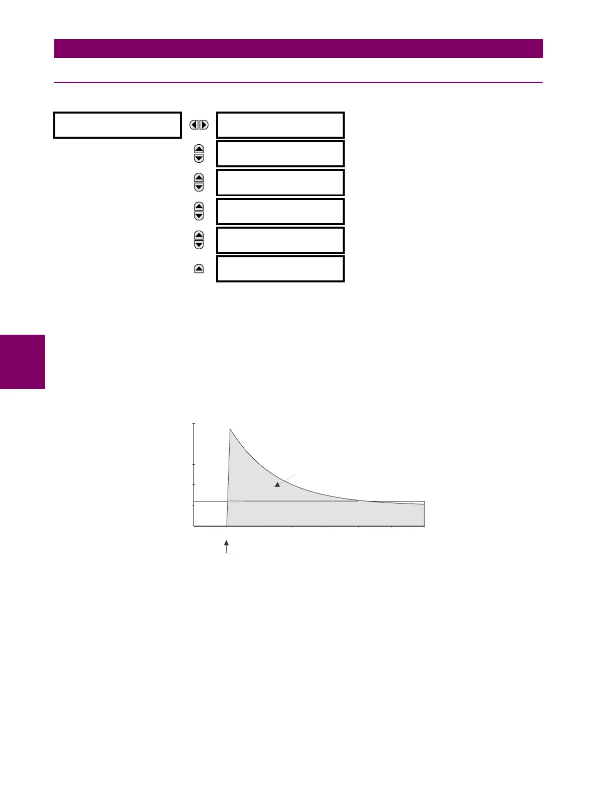
Without historical data on a particular feeder, some utilities assume an initial cold load current of about 500% of normal
load, decaying to 300% after 1 second, 200% after 2 seconds, and 150% after 3 seconds.
Figure 5–135: TYPICAL COLD LOAD PICKUP CHARACTERISTIC
There are two methods of initiating the operation of this feature.
The first initiation method is intended to automatically respond to a loss of the source to the feeder, by detecting that all
phase currents have declined to zero for some time. When zero current on all phases has been detected, a timer is started.
This timer is set to an interval after which it is expected the normal load diversity will have been lost, so setting groups are
not changed for short duration outages. After the delay interval, the output operand is set.
The second initiation method is intended to automatically respond to an event that will set an operand, such as an operator-
initiated virtual input. This second method of initiation sets the output operand immediately.
Both initiating inputs can be inhibited by a blocking input. Once cold load pickup is in operation, the output operand will
remain set until at least one phase of the load has returned to a level above 2% of CT nominal for the interval programmed
by the
ON-LOAD TIME BEFORE RESET setting has expired. The reset delay interval is intended to be set to a period until the
feeder load has decayed to normal levels, after which other features may be used to switch setting groups.
COLD LOAD PICKUP 1
COLD LOAD 1
FUNCTION: Disabled
Range: Disabled, Enabled
MESSAGE
COLD LOAD 1 PICKUP
SOURCE: SRC 1
Range: SRC 1, SRC 2, SRC 3, SRC 4
MESSAGE
COLD LOAD 1 INIT:
Off
Range: FlexLogic operand
MESSAGE
COLD LOAD 1 BLK:
Off
Range: FlexLogic operand
MESSAGE
OUTAGE TIME BEFORE
COLD LOAD1: 1000 s
Range: 0 to 1000 s in steps of 1
MESSAGE
ON-LOAD TIME BEFORE
RESET1: 100.000
Range: 0.000 to 1000 000.000 s in steps of 0.001
832760A1.CDR
time (seconds)
Current (% of normal)
0
100
200
300
400
500
-10123456
OUTAGE
PICKUP
PICKUP
LOAD ENERGIZED
X
NORMAL TRIP SETTING