6-24 F60 Feeder Protection System GE Multilin
6.3 METERING 6 ACTUAL VALUES
6
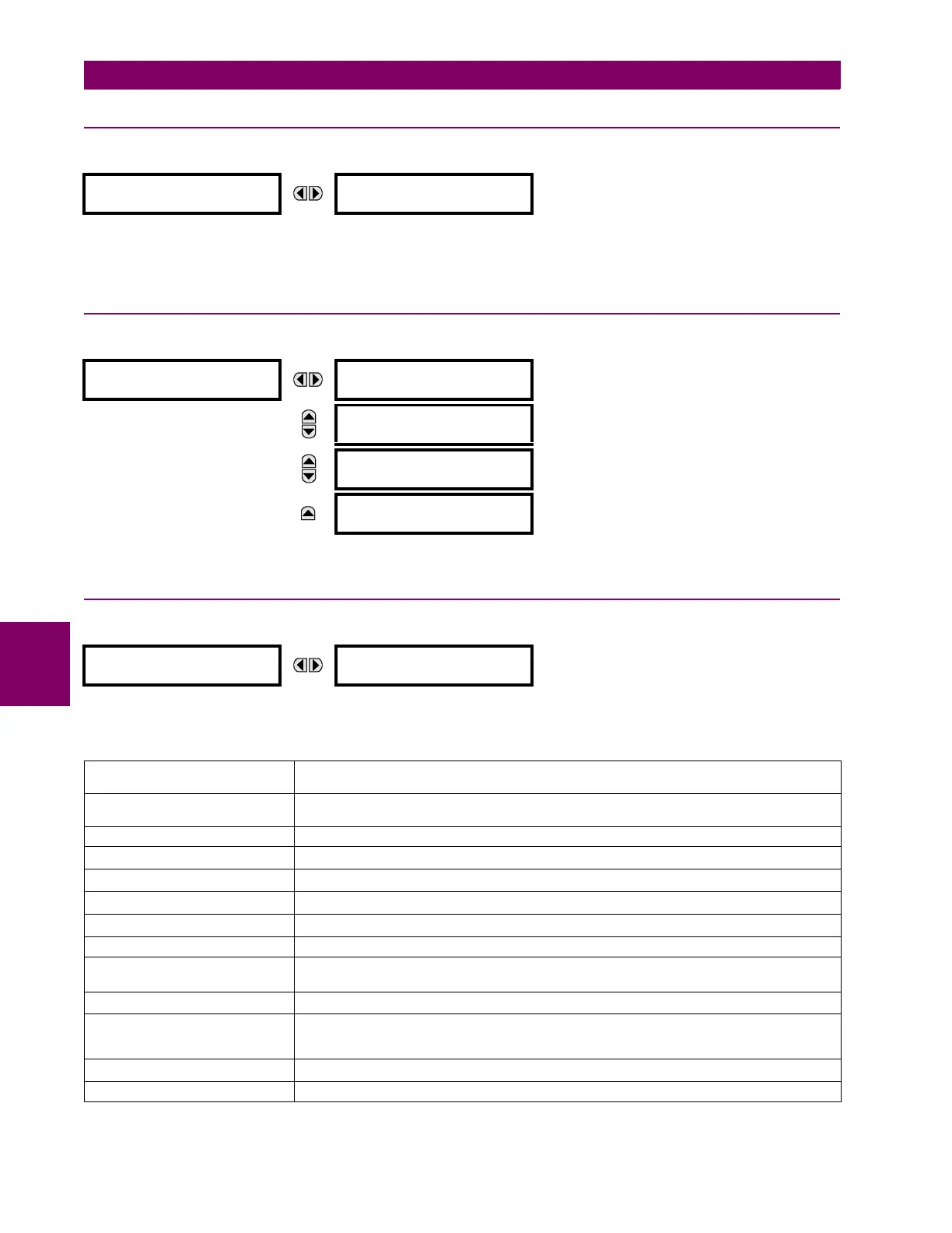
6.3.5 TRACKING FREQUENCY
PATH: ACTUAL VALUES METERING TRACKING FREQUENCY
The tracking frequency is displayed here. The frequency is tracked based on the selection of the reference source with the
FREQUENCY AND PHASE REFERENCE setting in the SETTINGS SYSTEM SETUP POWER SYSTEM menu. See the Power
System section of chapter 5 for details.
6.3.6 FREQUENCY RATE OF CHANGE
PATH: ACTUAL VALUES METERING FREQUENCY RATE OF CHANGE
The metered frequency rate of change for the frequency rate of change elements is shown here.
6.3.7 FLEXELEMENTS
PATH: ACTUAL VALUES METERING FLEXELEMENTS FLEXELEMENT 1(8)
The operating signals for the FlexElements are displayed in pu values using the following definitions of the base units.
TRACKING FREQUENCY
TRACKING FREQUENCY:
60.00 Hz
FREQUENCY RATE
OF CHANGE
FREQUENCY RATE OF
CHANGE 1: 0.00 Hz/s
MESSAGE
FREQUENCY RATE OF
CHANGE 2: 0.00 Hz/s
MESSAGE
FREQUENCY RATE OF
CHANGE 3: 0.00 Hz/s
MESSAGE
FREQUENCY RATE OF
CHANGE 4: 0.00 Hz/s
FLEXELEMENT 1
FLEXELEMENT 1
OpSig: 0.000 pu
Table 6–2: FLEXELEMENT BASE UNITS (Sheet 1 of 2)
BREAKER ARCING AMPS
(Brk X Arc Amp A, B, and C)
BASE = 2000 kA
2
× cycle
DCmA BASE = maximum value of the
DCMA INPUT MAX setting for the two transducers configured
under the +IN and –IN inputs.
FAULT LOCATION BASE = Line Length as specified in Fault Report
FREQUENCY f
BASE
= 1 Hz
FREQUENCY RATE OF CHANGE df/dt
BASE
= 1 Hz/s
PHASE ANGLE ϕ
BASE
= 360 degrees (see the UR angle referencing convention)
POWER FACTOR PF
BASE
= 1.00
RTDs BASE = 100°C
SENSITIVE DIR POWER
(Sns Dir Power)
P
BASE
= maximum value of 3 × V
BASE
× I
BASE
for the +IN and –IN inputs of the sources
configured for the sensitive power directional element(s).
SOURCE CURRENT I
BASE
= maximum nominal primary RMS value of the +IN and –IN inputs
SOURCE ENERGY
(Positive and Negative Watthours,
Positive and Negative Varhours)
E
BASE
= 10000 MWh or MVAh, respectively
SOURCE POWER P
BASE
= maximum value of V
BASE
× I
BASE
for the +IN and –IN inputs
SOURCE THD & HARMONICS BASE = 1%