GE Multilin F60 Feeder Protection System 5-201
5 SETTINGS 5.6 GROUPED ELEMENTS
5
EXAMPLE 5: INTERNAL LOW-CURRENT, HIGH-LOAD SINGLE-LINE-TO-GROUND FAULT WITH NO FEED FROM
THE GROUND
Given the following inputs: IA = 1.10 pu ∠0°, IB = 1.0 pu ∠–120°, IC = 1.0 pu ∠120°, and IG = 0.0 pu ∠0°
The relay calculates the following values:
I_0 = 0.033 pu ∠0°, I_2 = 0.033 pu ∠0°, and I_1 = 1.033 pu ∠0°
Igd = abs(3 × 0.0333 + 0.0) = 0.10 pu, IR0 = abs(3 × 0.033 – (0.0)) = 0.10 pu, IR2 = 3 × 0.033 = 0.10 pu,
IR1 = 1.033 / 8 = 0.1292 pu, and Igr = 0.1292 pu
Despite very low fault current level the differential current is above 75% of the restraining current.
EXAMPLE 6: INTERNAL HIGH-CURRENT SINGLE-LINE-TO-GROUND FAULT WITH NO FEED FROM THE GROUND
Given the following inputs: IA = 10 pu ∠0°, IB = 0 pu, IC = 0 pu, and IG = 0 pu
The relay calculates the following values:
I_0 = 3.3 pu ∠0°, I_2 = 3.3 pu ∠0°, and I_1 = 3.3 pu ∠0°
Igd = abs(3 × 3.3 + 0.0) = 10 pu, IR0 = abs(3 × 3.3 – (0.0)) = 10 pu, IR2 = 3 × 3.3 = 10 pu, IR1 = 3 × (3.33–3.33) = 0
pu, and Igr = 10 pu
The differential current is 100% of the restraining current.
5.6.8 NEGATIVE-SEQUENCE CURRENT
a) MAIN MENU
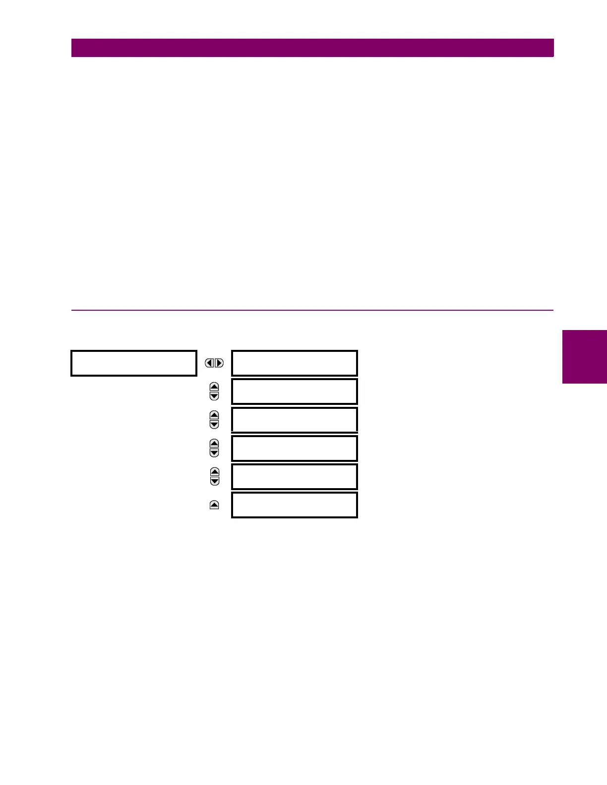
PATH: SETTINGS GROUPED ELEMENTS SETTING GROUP 1(6) NEGATIVE SEQUENCE CURRENT
For additional information on the negative sequence time overcurrent curves, refer to the Inverse Time Overcurrent Curves
section earlier.
NEGATIVE SEQUENCE
CURRENT
NEG SEQ TOC1
See page 5–202.
MESSAGE
NEG SEQ TOC2
See page 5–202.
MESSAGE
NEG SEQ IOC1
See page 5–203.
MESSAGE
NEG SEQ IOC2
See page 5–203.
MESSAGE
NEG SEQ DIR OC1
See page 5–204.
MESSAGE
NEG SEQ DIR OC2
See page 5–204.