5-122 F60 Feeder Protection System GE Multilin
5.4 SYSTEM SETUP 5 SETTINGS
5
5.4.7 PHASOR MEASUREMENT UNIT
a) MAIN MENU
PATH: SETTINGS SYSTEM SETUP PHASOR MEASUREMENT UNIT
The F60 is provided with an optional phasor measurement unit feature. This feature is specified as a soft-
ware option at the time of ordering. The number of phasor measurement units available can also depend
on this option. Using the order code for your device, see the order codes in chapter 2 for details.
UR Synchrophasor Implementation
PHASORS are used within protection relays. If these phasors are referenced to a common time base they are referred to as
a SYNCHROPHASOR. A vastly improved method for tracking power system dynamic phenomena for improved power system
monitoring, protection, operation, and control can be realized if Synchrophasors from different locations within the power
system are networked to a central location.
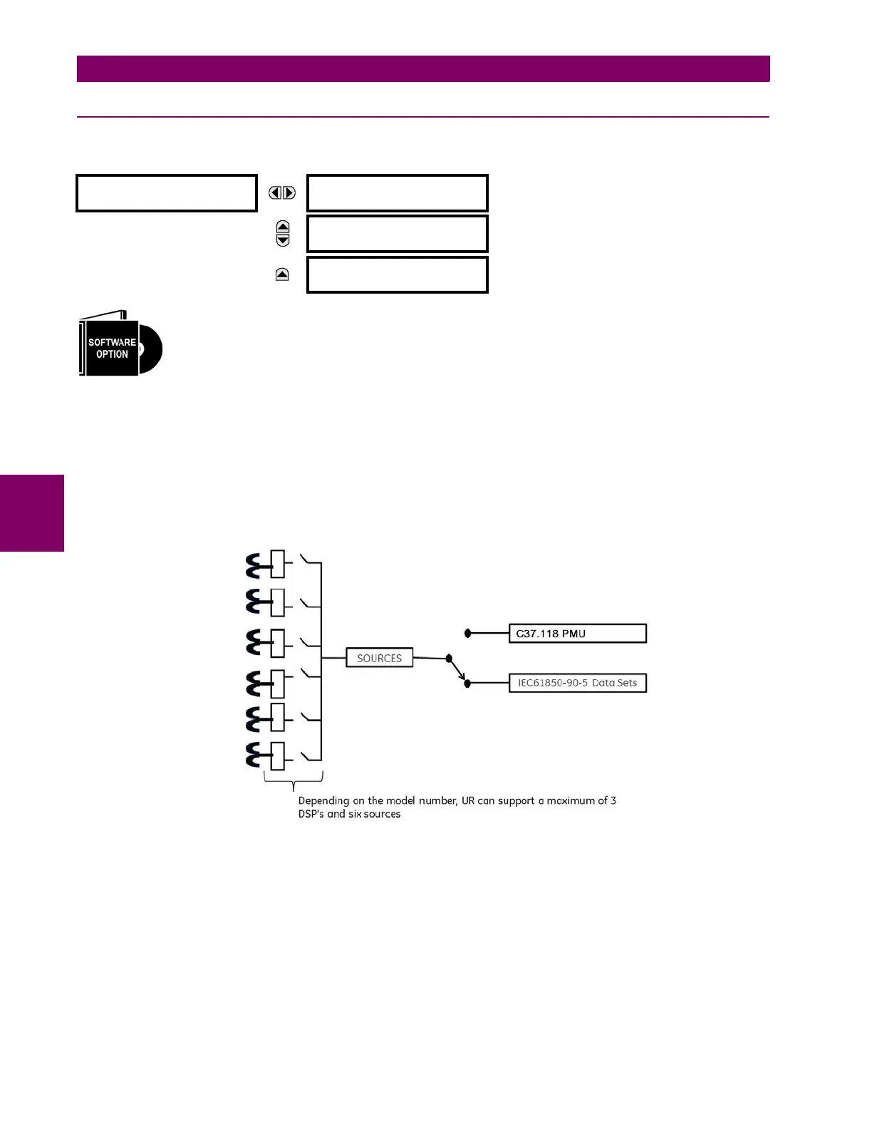
The F60 offers PMU features over two communication standards, IEC 61850-9-5 and IEEE C37.118. The figure shows
complete Synchrophasor implementation.
Figure 5–41: COMPLETE SYNCHROPHASOR IMPLEMENTATION
UR Implementation of IEC 61850-90-5
Synchrophasor data as measured and calculated by phasor measurement units (PMUs) is used to assess the condition of
the electrical power network. The IEEE C37.118 standards define synchrophasors and related message formats to transmit
synchrophasor data. Synchrophasor streaming via IEEE C37.118 has proven to work but the desire to have a communica-
tion mechanism that is compliant with the concept of IEC 61850 has led to the development of IEC 61850-90-5. The IEC
61850-90-5 standard defines the packet structure for multicast routing of streamed Sampled Value (SV) known as R-SV.
PHASOR MEASUREMENT
UNIT
PHASOR MEASUREMENT
UNIT 1
See below.
MESSAGE
AGGREGATOR
UNIT 1
See page 5-141.
MESSAGE
IEC 90-5 MSVCB
CONFIGURATION
See page 5–143.