GE Multilin F60 Feeder Protection System 5-225
5 SETTINGS 5.6 GROUPED ELEMENTS
5
5.6.11 SENSITIVE DIRECTIONAL POWER (ANSI 32)
PATH: SETTINGS GROUPED ELEMENTS SETTING GROUP 1(6) POWER SENSITIVE DIRECTIONAL POWER
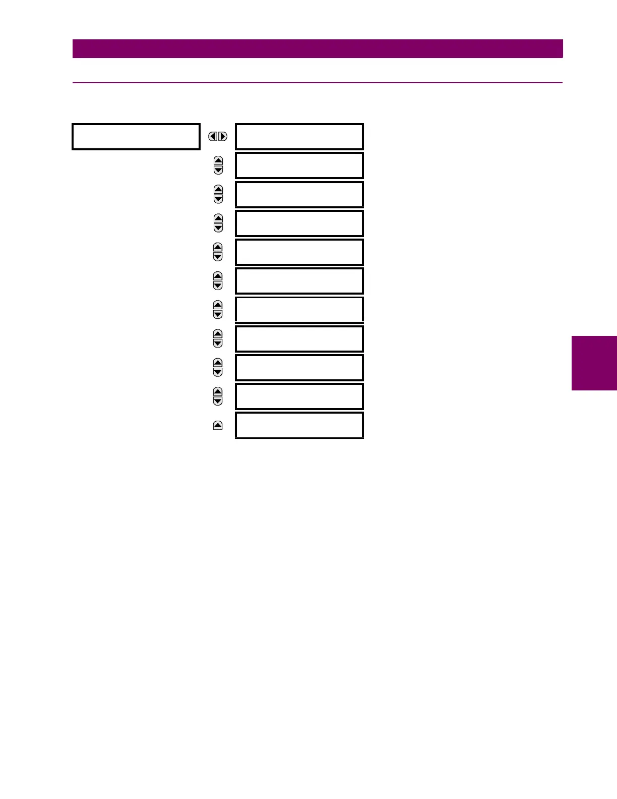
DIRECTIONAL POWER 1(2)
The sensitive directional power element responds to three-phase directional power and is designed for reverse power and
low forward power applications for synchronous machines or interconnections involving co-generation. The relay measures
the three-phase power from either full set of wye-connected VTs or full-set of delta-connected VTs. In the latter case, the
two-wattmeter method is used. Refer to the UR-series metering conventions section in chapter 6 for details regarding the
active and reactive powers used by the sensitive directional power element.
The element has an adjustable characteristic angle and minimum operating power as shown in the Directional power char-
acteristic diagram. The element responds to the following condition:
(EQ 5.29)
where: P and Q are active and reactive powers as measured per the UR-series metering convention,
θ is a sum of the element characteristic (
DIR POWER 1 RCA) and calibration (DIR POWER 1 CALIBRATION) angles, and
SMIN is the minimum operating power
The operating quantity is displayed in the ACTUAL VALUES METERING SENSITIVE DIRECTIONAL POWER 1(2) actual
value. The element has two independent (as to the pickup and delay settings) stages for alarm and trip, respectively.
DIRECTIONAL
POWER 1
DIR POWER 1
FUNCTION: Disabled
Range: Disabled, Enabled
MESSAGE
DIR POWER 1
SOURCE: SRC 1
Range: SRC 1, SRC 2, SRC 3, SRC 4
MESSAGE
DIR POWER 1
RCA: 0°
Range: 0 to 359° in steps of 1
MESSAGE
DIR POWER 1
CALIBRATION: 0.00°
Range: 0 to 0.95° in steps of 0.05
MESSAGE
DIR POWER 1 STG1
SMIN: 0.100 pu
Range: –1.200 to 1.200 pu in steps of 0.001
MESSAGE
DIR POWER 1 STG1
DELAY: 0.50 s
Range: 0.00 to 600.00 s in steps of 0.01
MESSAGE
DIR POWER 1 STG2
SMIN: 0.100 pu
Range: –1.200 to 1.200 pu in steps of 0.001
MESSAGE
DIR POWER 1 STG2
DELAY: 20.00 s
Range: 0.00 to 600.00 s in steps of 0.01
MESSAGE
DIR POWER 1 BLK:
Off
Range: FlexLogic operand
MESSAGE
DIR POWER 1
TARGET: Self-Reset
Range: Self-Reset, Latched, Disabled
MESSAGE
DIR POWER 1
EVENTS: Disabled
Range: Disabled, Enabled