GE Multilin F60 Feeder Protection System 5-167
5 SETTINGS 5.5 FLEXLOGIC
5
The FLEXELEMENT 1 HYSTERESIS setting defines the pickup–dropout relation of the element by specifying the width of the
hysteresis loop as a percentage of the pickup value as shown in the FlexElement direction, pickup, and hysteresis diagram.
The
FLEXELEMENT 1 DT UNIT setting specifies the time unit for the setting FLEXELEMENT 1 dt. This setting is applicable only if
FLEXELEMENT 1 COMP MODE is set to “Delta”. The FLEXELEMENT 1 DT setting specifies duration of the time interval for the
rate of change mode of operation. This setting is applicable only if
FLEXELEMENT 1 COMP MODE is set to “Delta”.
This
FLEXELEMENT 1 PKP DELAY setting specifies the pickup delay of the element. The FLEXELEMENT 1 RST DELAY setting
specifies the reset delay of the element.
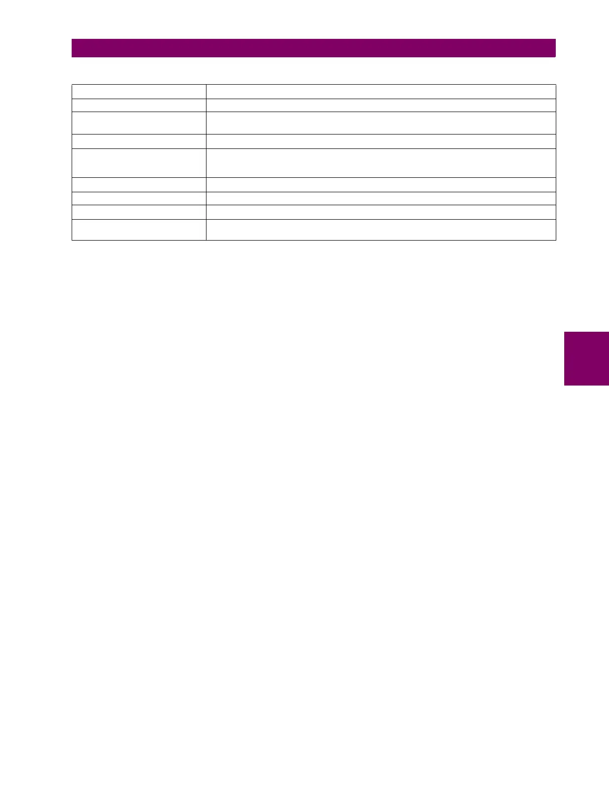
POWER FACTOR PF
BASE
= 1.00
RTDs BASE = 100°C
SENSITIVE DIR POWER
(Sns Dir Power)
P
BASE
= maximum value of 3 × V
BASE
× I
BASE
for the +IN and –IN inputs of the sources
configured for the sensitive power directional element(s).
SOURCE CURRENT I
BASE
= maximum nominal primary RMS value of the +IN and –IN inputs
SOURCE ENERGY
(Positive and Negative Watthours,
Positive and Negative Varhours)
E
BASE
= 10000 MWh or MVAh, respectively
SOURCE POWER P
BASE
= maximum value of V
BASE
× I
BASE
for the +IN and –IN inputs
SOURCE THD & HARMONICS BASE = 1%
SOURCE VOLTAGE V
BASE
= maximum nominal primary RMS value of the +IN and –IN inputs
SYNCHROCHECK
(Max Delta Volts)
V
BASE
= maximum primary RMS value of all the sources related to the +IN and –IN inputs
Table 5–21: FLEXELEMENT BASE UNITS