GE Multilin F60 Feeder Protection System 5-187
5 SETTINGS 5.6 GROUPED ELEMENTS
5
where: ,
,
ECA = element characteristic angle and IG = ground current
When
NEUTRAL DIR OC1 POL VOLT is set to “Measured VX”, one-third of this voltage is used in place of V_0. The following
figure explains the usage of the voltage polarized directional unit of the element.
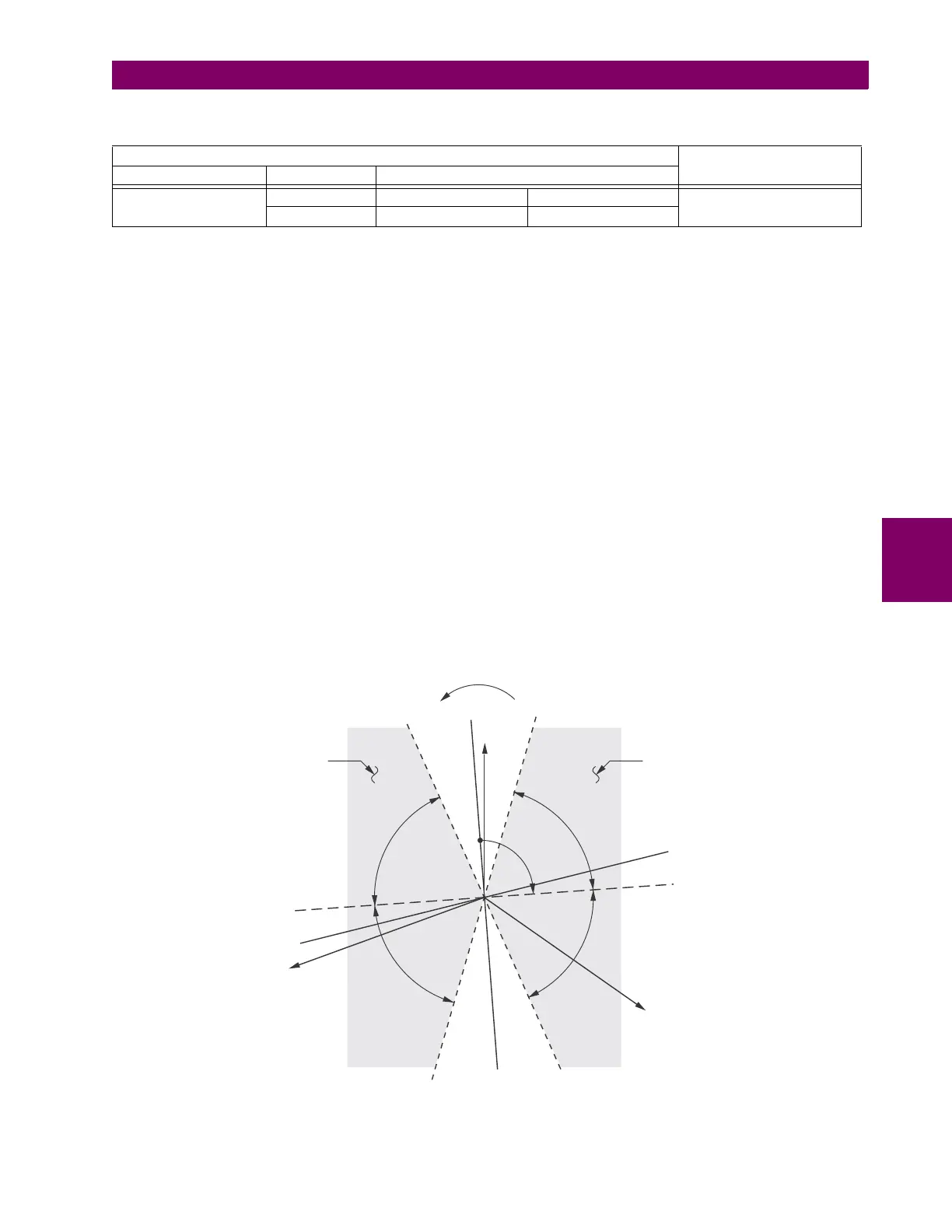
The figure below shows the voltage-polarized phase angle comparator characteristics for a phase A to ground fault, with:
• ECA = 90° (element characteristic angle = centerline of operating characteristic)
• FWD LA = 80° (forward limit angle = the ± angular limit with the ECA for operation)
• REV LA = 80° (reverse limit angle = the ± angular limit with the ECA for operation)
The element incorporates a current reversal logic: if the reverse direction is indicated for at least 1.25 of a power system
cycle, the prospective forward indication is delayed by 1.5 of a power system cycle. The element is designed to emulate an
electromechanical directional device. Larger operating and polarizing signals results in faster directional discrimination
bringing more security to the element operation.
The forward-looking function is designed to be more secure as compared to the reverse-looking function, and therefore,
should be used for the tripping direction. The reverse-looking function is designed to be faster as compared to the forward-
looking function and should be used for the blocking direction. This allows for better protection coordination.
The above bias should be taken into account when using the neutral directional overcurrent element to directionalize other
protection elements.
Figure 5–76: NEUTRAL DIRECTIONAL VOLTAGE-POLARIZED CHARACTERISTICS
Table 5–31: QUANTITIES FOR "MEASURED IG" CONFIGURATION
DIRECTIONAL UNIT
OVERCURRENT UNIT
POLARIZING MODE DIRECTION COMPARED PHASORS
Voltage
Forward –V_0 + Z_offset × IG/3 IG × 1∠ECA
I
op
= |IG|
Reverse –V_0 + Z_offset × IG/3 –IG × 1∠ECA
V_0
1
3
---
VAG VBG VCG++()zero sequence voltage==
I_0
1
3
---
IN
1
3
---
IA IB IC++()zero sequence current== =
827805A1.CDR
VAG
(reference)
VBG
VCG
–3I_0 line
3I_0 line
ECA line
–ECA line
LA
LA
LA
LA
ECA
FWD LA
line
FWD Operating
Region
REV Operating
Region
FWD LA
line
REV LA
line
REV LA
line
–3V_0 line
3V_0 line

 Loading...


