GE Multilin F60 Feeder Protection System 5-259
5 SETTINGS 5.7 CONTROL ELEMENTS
5
Combinations of these events are possible: for example, an arcing high impedance, downed conductor fault. The Hi-Z ele-
ment is intended to detect high impedance faults that arc and to differentiate those that are downed conductors from those
that are not. It should be noted that no known technology can detect all Hi-Z faults.
The Hi-Z element was primarily designed for solidly grounded systems. The similar Hi-Z element in the DFM200 relay has
been tested with some success on impedance grounded systems as well. However, there are no guarantees of certain
operation of the high impedance fault detection element on non-solidly grounded systems.
The Hi-Z data collection consists of RMS Data Capture and Hi-Z Data capture:
• RMS Data Capture: The RMS data captures are triggered by two-cycle Hi-Z overcurrent conditions, loss of load con-
ditions, and high arc confidence conditions. Captures triggered by loss of load and high arc confidence conditions are
saved to a temporary capture table, and deleted if the event does not result in an Arcing or Downed Conductor condi-
tion. The relay maintains a history of four captures and utilizes a combination of age, priority and access for determin-
ing which capture to save.
The RMS data capture contains the two-cycle RMS values for the voltage and current for each of the phases and cur-
rent for the neutral channel. The capture frequency is half the system frequency. Each capture contains 1800 points.
• High-Z Data Capture: Hi-Z Data Captures are triggered and maintained in an identical manner as RMS Data Cap-
tures. The relay maintains four captures of 300 records each. The capture frequency is 1 Hz and the data collected is
defined in the following two tables.
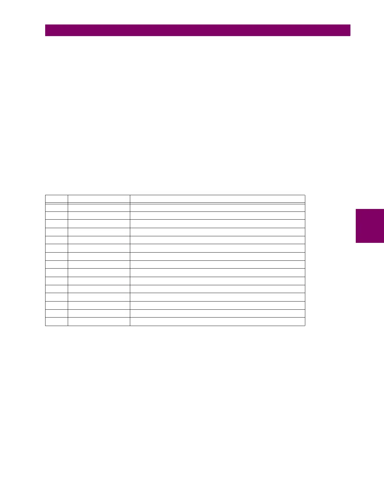
Table 5–35: HI-Z SPECIFIC DATA
# NAME DESCRIPTION
0 EadCounts Total number of EAD counts for the phase
1 ArcConfidence ArcConfidence for the phase
2 AccumArcConf Accumulated ArcConfidence for the phase
3 RmsCurrent The 2-cycle RMS current for the phase
4 HighROC Flag indicating a high rate of change was detected
5 IOC Flag indicating an instantaneous 2-cycle overcurrent was detected
6 LossOfLoad Flag indicating a loss of load was detected
7 EadZeroed Flag indicating that this phase’s EAD table was cleared
8 HighZArmed Flag indicating that this phase is armed for a high-Z detection
9 VoltageDip Flag indicating that a voltage dip was detected on this phase
10 HighEad Flag indicating that a high arc confidence occurred on this phase
11 ArcBurst Flag indicating that an arc burst was identified on this phase
12 VDisturbanceCc Cycle-to-cycle voltage disturbance
13 VDisturbanceAbs Absolute voltage disturbance
14 HarmonicRestraint Harmonic Restraint