5-276 F60 Feeder Protection System GE Multilin
5.7 CONTROL ELEMENTS 5 SETTINGS
5
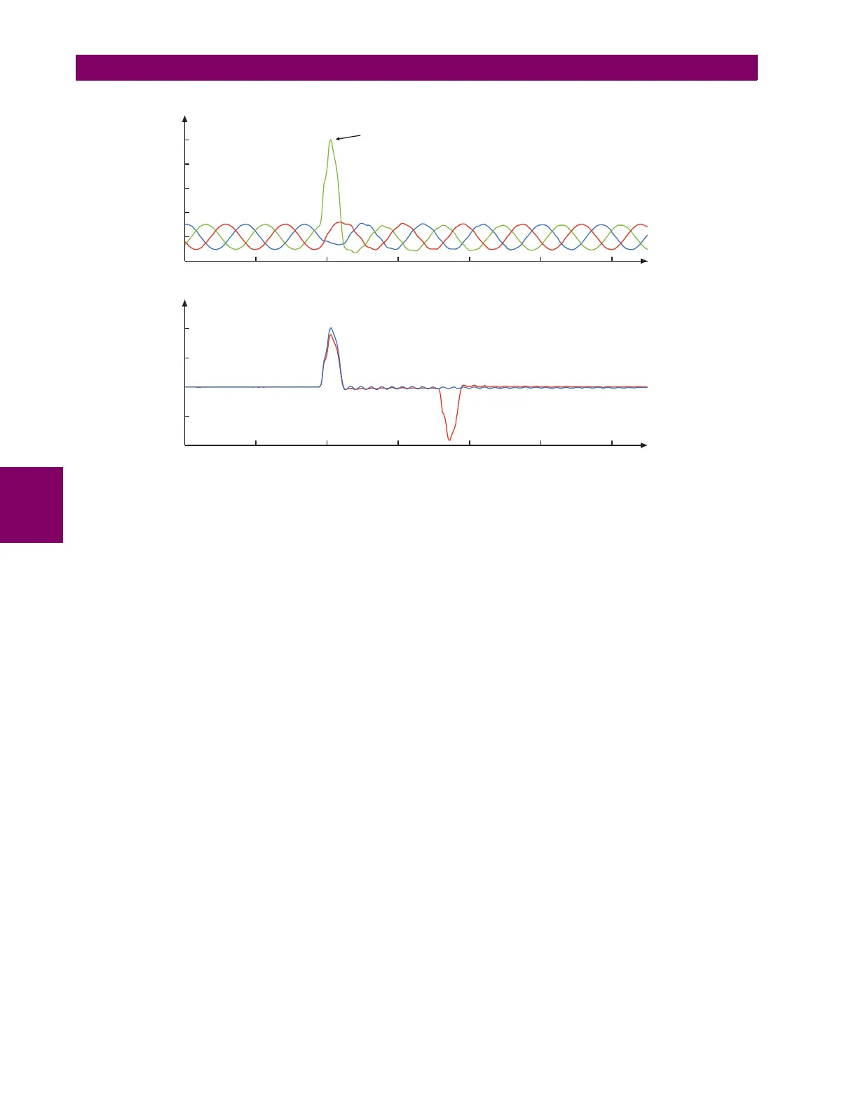
Figure 5–129: ILLUSTRATION OF THE INCIPIENT FAULT DETECTOR ALGORITHM
The following settings are available for each incipient cable fault detector.
• INCIPIENT FAULT 1 FUNCTION: This setting enable and disables operation of the incipient fault detection element.
• INCIPNT FLT 1 BLOCK: This setting is used to block operation of the incipient cable fault detector element. Assertion
of the FlexLogic™ operand assigned to this setting block operation.
• INCIPIENT FAULT 1 SOURCE: This setting selects a current source for the incipient cable fault detector element. This
source must be assigned a valid CT bank.
• INCIPIENT FAULT 1 PICKUP: This setting specifies pickup level of the overcurrent detector in per-unit values of the
CT nominal current.
• INCIPNT FLT 1 MODE: There are two modes of operation available for the incipient cable fault detector element. In
the “Number of counts” mode, a trip will be initiated only after the selected number of faults is detected. In the “Counts
per window” mode, a trip will be initiated only after the selected number of faults is detected within the time specified by
the INCIPNT FLT 1 DETECT WINDOW setting.
• INCIPIENT FLT 1 TRIP COUNTS NUMBER: This setting selects the number of faults required to initiate a trip.
• INCIPNT FLT 1 DETECT WINDOW: This setting specifies a time window for “Counts per window” mode of operation.
• INCIPIENT FAULT 1 RESET DELAY: This setting specifies a reset time for the output after the trip is initiated.
0.62 0.64 0.66 0.68 0.70 0.72 0.74
0
1.0
2.0
0.62 0.64 0.66 0.68 0.7 0.72 0.74
–2.0
–1.0
0
1.0
2.0
I
N
(neutral current)
I
FB
–0.5
Phase B
Phase C
Phase A
Incipient phase B fault
Current (amps)
Current (amps)
832774A1.CDR
PHASE CURRENTS
CALCULATED NEUTRAL AND
SUPERIMPOSED PHASE B CURRENT