3-36 F60 Feeder Protection System GE Multilin
3.3 DIRECT INPUT/OUTPUT COMMUNICATIONS 3 HARDWARE
3
The UR-series C37.94 communication module can be connected to the electrical interface (G.703, RS422, or X.21) of a
non-compliant digital multiplexer via an optical-to-electrical interface converter that supports the IEEE C37.94 standard,
shown as follows.
In 2008, GE Grid Solutions released revised modules 76 and 77 for C37.94 communication to enable multi-ended fault
location functionality with firmware 5.60 release and higher. All modules 76 and 77 shipped the change support this feature
and are fully backward compatible with firmware releases below 5.60. For customers using firmware release 5.60 and
higher, the module can be identified with "Rev D" printed on the module and is to be used on all ends of F60 communication
for two and three terminal applications. Failure to use it at all ends results in intermittent communication alarms. For cus-
tomers using firmware revisions below 5.60, it is not required to match the revision of the modules installed.
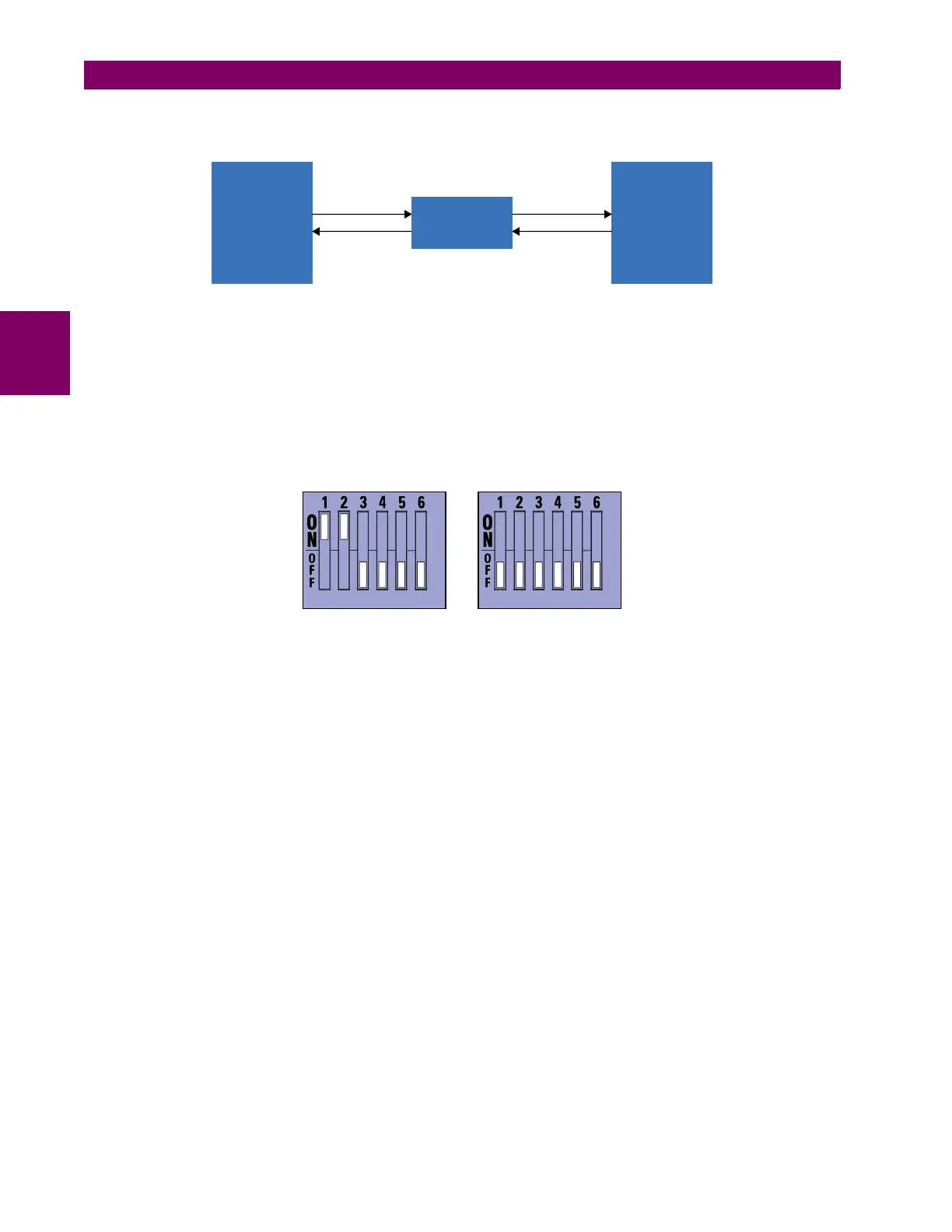
The UR-series C37.94 communication module has six switches to set the clock configuration. The following figure shows
the functions of these control switches.
For the internal timing mode, the system clock is generated internally. Therefore, the timing switch selection should be
internal timing for relay 1 and loop timed for relay 2. There must be only one timing source configured.
For the looped timing mode, the system clock is derived from the received line signal. Therefore, the timing selection
should be in loop timing mode for connections to higher order systems.
The IEEE C37.94 communications module cover removal procedure is as follows:
1. With power to the relay off, remove the IEEE C37.94 module (type 2G, 2H, 2I, 2J, 76 or 77 module) as follows. Record
the original location of the module to help ensure that the same or replacement module is inserted into the correct slot.
2. Simultaneously pull the ejector/inserter clips located at the top and at the bottom of each module in order to release the
module for removal.
3. Remove the module cover screw.
4. Remove the top cover by sliding it towards the rear and then lift it upwards.
5. Set the timing selection switches (channel 1, channel 2) to the desired timing modes (see description above).
6. Replace the top cover and the cover screw.
7. Re-insert the IEEE C37.94 module. Take care to ensure that the correct module type is inserted into the correct slot
position. The ejector/inserter clips located at the top and at the bottom of each module must be in the disengaged posi-
tion as the module is smoothly inserted into the slot. Once the clips have cleared the raised edge of the chassis,
engage the clips simultaneously. When the clips have locked into position, the module is fully inserted.
UR-series
device
up to 2 km
IEEE C37.94
converter
RS422
interface
842756A2.CDR
IEEE C37.94
fiber interface
Digital
multiplexer
with EIA-422
interface
842753A2.CDR
Internal timing mode
Loop timing mode
(factory default)