GE HEALTHCARE
DIRECTION 5394141, REVISION 5 LOGIQ™ P5 SEVICE MANUAL
Section 5-5 - Top Console 5-27
5-5-1-1 KEYBOARD Signal I/O
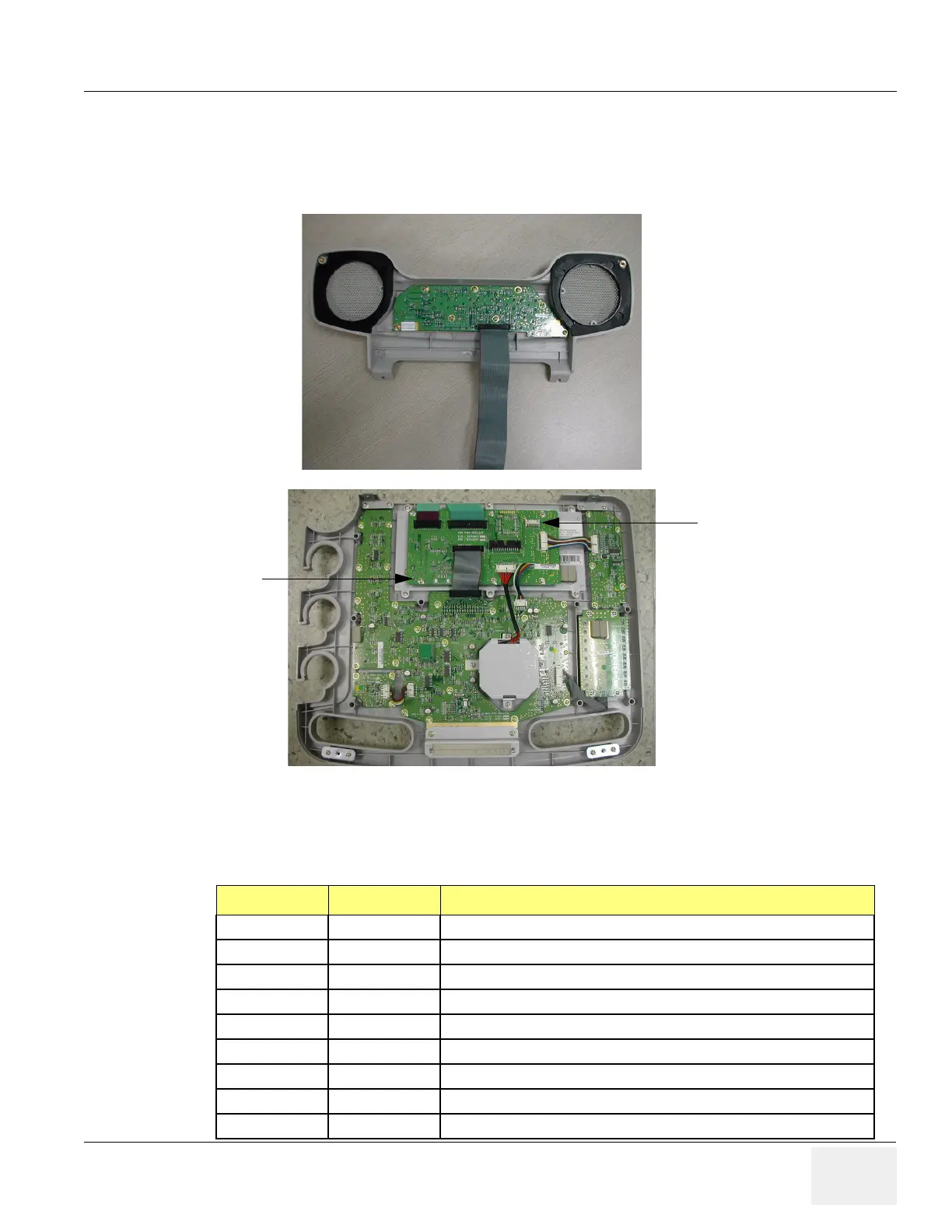
Main keyboard assy have two main external I/O connectors. One is for USB connection to scan system
for main control signal interface, the other is for 5V power supply and momentary switch of scan system
with hard drive operation indicator.
Figure 5-26 Main Keyboard and Sub Keyboard connection to system
Table 5-1 CON1 Connector Signal I/O
Pin Number Pin Name Signal Path
1 HDD- L1SYSCON > Backplane > Main Keyboard> Sub Keyboard
2 HDD+ L1SYSCON > Backplane > Main Keyboard> Sub Keyboard
3 Momentary S/W L1SYSCON > Backplane > Main Keyboard> Sub Keyboard
4GND
10 GND
11 GND
12 GND
13 KBD PWR APS/APS Pro > Backplane > Main Keyboard > Sub Keyboard
14 KBD PWR APS/APS Pro > Backplane > Main Keyboard> Sub Keyboard
(a)Sub keyboard
(b)Main Keyboard
USB
CON1