
T
Travis PierceNov 23, 2025
What to do if GE Measuring Instruments screen always reads the wettest value?
- AAnna MartinNov 23, 2025
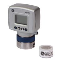
If your GE Measuring Instruments screen always reads the wettest programmed moisture calibration value while displaying dew/frost point, it could be due to: * Probe saturation: Liquid water may be present on the sensor surface or across electrical connections. Clean the sensor and sensor shield as described in document 916-064, Basic Hygrometry Principles, and then reinstall the sensor. * Shorted circuit: Run “dry gas” over the sensor surface. If the high reading persists, the probe is likely shorted and should be returned to the factory for evaluation. * Sensor contamination: Clean the sensor and sensor shield as described in document 916-064, Basic Hygrometry Principles, and then reinstall the sensor. * Improper cable connection: Check the cable connections to both the probe and...