Chapter 1. Installation
28 moisture.IQ User’s Manual
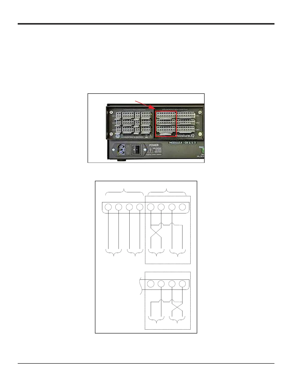
1.11 Connecting an Auxiliary Device
moisture.IQ can power an auxiliary device (such as a loop power transmitter) in which the connection is +24V
to Aux 1 or 2. For external power devices with output directly connected to the auxiliary device, you can use
aux 1 or 2 with respect to RTN (pin 5). Make the connections to the right-side group of probe connections (AUX
IN/OUT
and ALARMS) that are rated for non-hazardous area use. Users set the voltage/current for the auxiliary
input and the electronics will automatically switch the circuits, so the moisture.IQ has no physical switch to
toggle. Figure 23 and Figure 24 below show the connections and wiring for auxiliary devices.
Figure 23: Auxiliary Connections
Figure 24: Auxiliary Device Wiring Diagram
Auxiliary Connections
++
87654321
Analog Out
Volt/Current
A
Analog Out
Volt/Current
B
Aux In 1 Aux In 2
-
External Power Mode
Loop Powered Mode
+
Aux In 2Aux In 1
56 78
-
+
-
ANALOG OUT
--
++++
----
AUX IN
OR
.
.
+
 Loading...