Chapter 1. Installation
20 moisture.IQ User’s Manual
1.9.3.2 Moisture Image Series Probes (cont.)
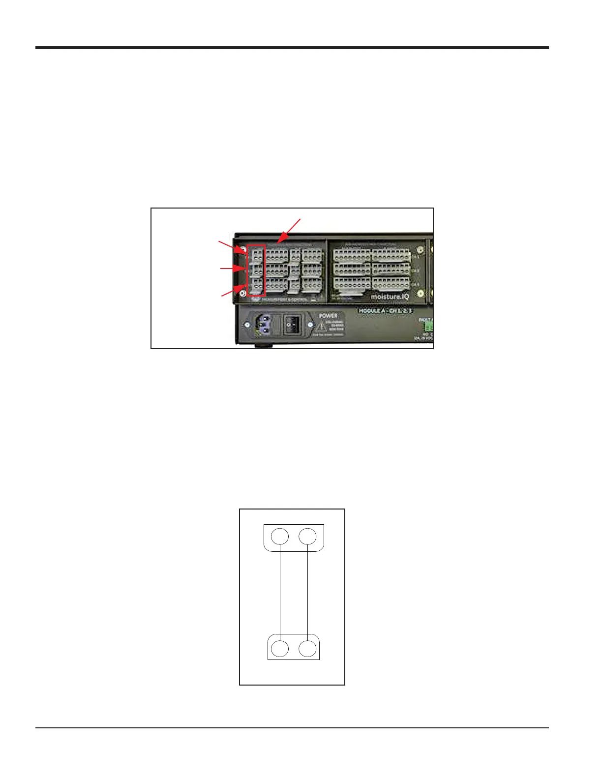
If the Moisture Image Series probe requires assembly, complete that task before proceeding. Then, connect the
probe cable to the terminal block labeled MIS on the back panel of the electronics unit (see Figure 16 below).
You can connect the Moisture Image Series Probe to any channel. However, if you are also using other sensors
such as M-Series probes, be sure to connect the Moisture Image Series probe to an unassigned channel.
IMPORTANT: Check the Calibration Data Sheets of all installed sensors to determine which channels already
have probes assigned to them.
Figure 16: MIS Probe Connections
Note: Additional MIS probes may be connected to CH4, CH5 and CH6 in the Module B connector group on the
right side of the back panel.
After you make the back panel connections, connect the other end of the probe cable to the Moisture Image
Series probe per the wiring diagram in Figure 17. Trim all other flying leads from the cable flush with the
jacket.
After you complete the Moisture Image Series probe connections, you must activate the probe on the installed
channel as described in “The Probe Configuration Screen” on page 60.
Figure 17: MIS Probe Cable Wiring Diagram
Module A - CH2
MIS Probe Connections
Module A - CH3
Module A - CH1
MISP 1
or MISP 2
WHITE
BLACK
21
MIS
 Loading...