GE Multilin G60 Generator Protection System 3-45
3 HARDWARE 3.4 FIELD AND STATOR GROUND MODULES
3
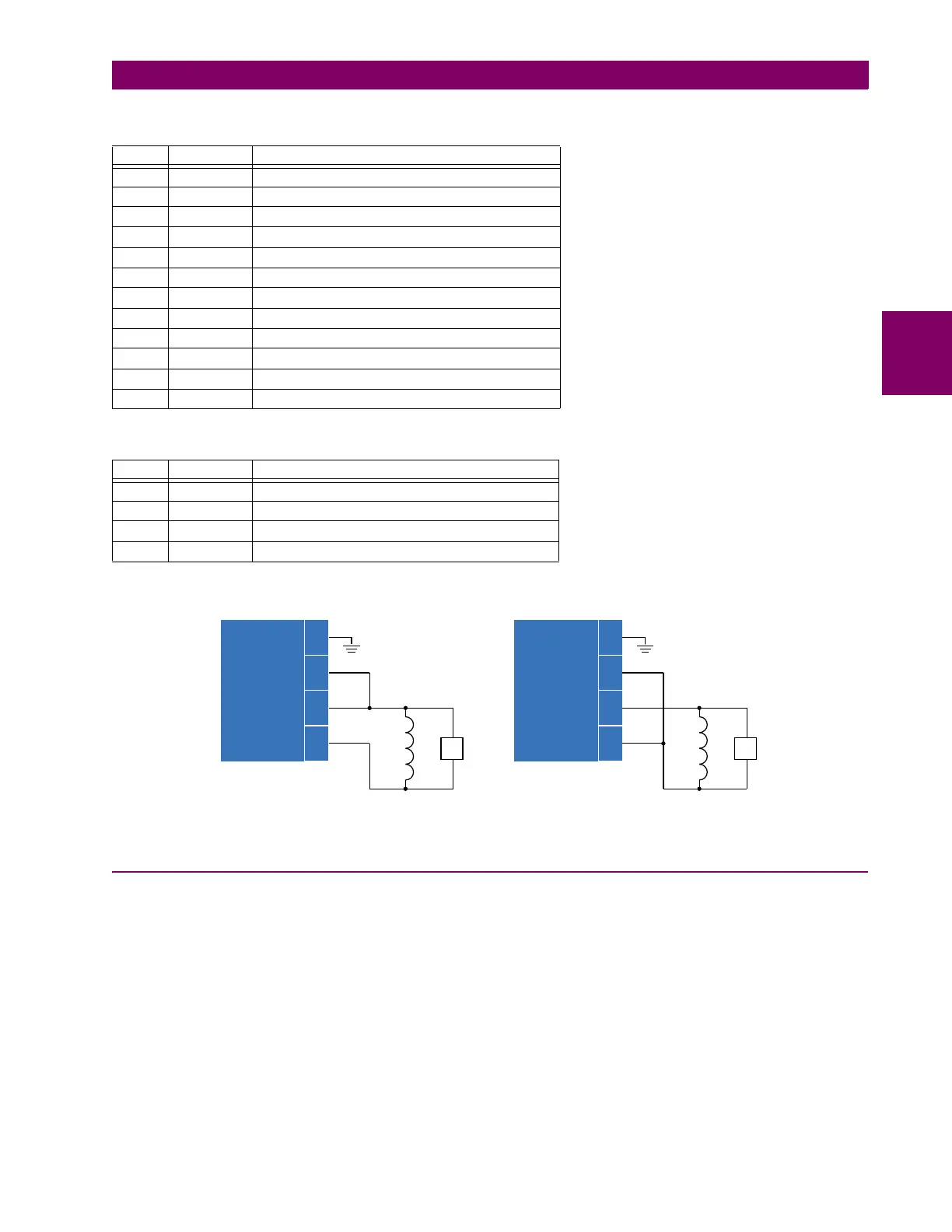
The following diagram illustrates how to wire the GPM-F-L module for both single-point injection and double-point injection.
Figure 3–53: CONNECTING THE FIELD GROUND PROTECTION MODULE
3.4.3 FIELD GROUND HIGH-VOLTAGE PROTECTION SYSTEM
The field ground high-voltage protection system consists of two modules: the field ground protection high-voltage module
(GPM-F-HM) and the field ground protection high-voltage resistor box (GPM-F-R). The mounting and dimension diagrams
are shown below (all dimensions are in inches).
Table 3–7: GPM-F-L PIN ASSIGNMENTS FOR CONNECTOR B
PIN LABEL DEFINITION
1 CH1(+) RS485 channel 1 positive
2 CH1(–) RS485 channel 1 negative
3 COM RS485 common
4 CH2(+) RS485 channel 2 positive
5 CH2(–) RS485 channel 2 negative
6 IN3 Contact input 3
7 IN2 Contact input 2
8 IN1 Contact input 1
9 COM Contact input common
10 NC Relay NC (normally closed)
11 COM Relay common
12 NO Relay NO (normally open)
Table 3–8: GPM-F-L PIN ASSIGNMENTS FOR CONNECTOR C
PIN LABEL DEFINITION
1 FGND Field ground
2 F1 Injection to excitation positive
3 F(–) Injection to excitation negative / excitation negative
4 F(+) Excitation positive
$&'5
)LHOGJURXQG
SURWHFWLRQ
PRGXOH
*30)+0
&
&
&
&
&RQQHFWLRQIRU
GRXEOHSRLQWLQMHFWLRQ
)LHOGJURXQG
SURWHFWLRQ
PRGXOH
*30)+0
)
&
&
&
&
)
&RQQHFWLRQIRU
VLQJOHSRLQWLQMHFWLRQ
(;
²
)²
(;
²
)