GE Multilin G60 Generator Protection System 3-63
3 HARDWARE 3.5 MANAGED ETHERNET SWITCH MODULES
3
The wiring for the managed Ethernet switch module is shown below.
Figure 3–74: MANAGED ETHERNET SWITCH MODULE WIRING
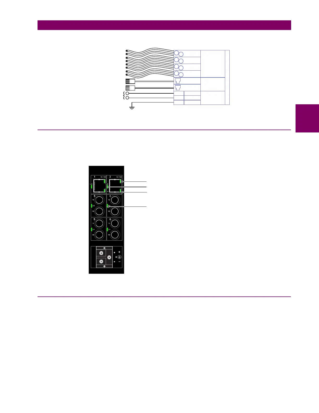
3.5.3 MANAGED SWITCH LED INDICATORS
The 10/100Base-T and 100Base-FX ports have LED indicators to indicate the port status.
The 10/100Base-T ports have three LEDs to indicate connection speed, duplex mode, and link activity. The 100Base-FX
ports have one LED to indicate linkup and activity.
Figure 3–75: ETHERNET SWITCH LED INDICATORS
3.5.4 INITIAL SETUP OF THE ETHERNET SWITCH MODULE
a) DESCRIPTION
Upon initial power up of a G60 device with an installed Ethernet switch, the front panel trouble LED will be illuminated and
the
ENET MODULE OFFLINE error message will be displayed. It will be necessary to configure the Ethernet switch and then
place it online. This involves two steps:
1. Configuring the network settings on the local PC.
2. Configuring the G60 switch module through EnerVista UR Setup.
These procedures are described in the following sections. When the G60 is properly configured, the LED will be off and the
error message will be cleared.
$&'5
%DVH);
%DVH);
7[
5[
7[
5[
*5281'
³
:D
:E
:D
3RZHUVXSSO\
&RSSHU
SRUWV
&38 67
00ILEHURSWLFFDEOH
00ILEHURSWLFFDEOH
%DVH7
%DVH7
%DVH);
7[
5[
%DVH);
7[
5[
)LEHU
SRUWV
00ILEHURSWLFFDEOH
00ILEHURSWLFFDEOH
²
%DVH7FDEOH
%DVH7FDEOH
WR9'&
WR9$&
842868A2.CDR
Connection speed indicator (OFF = 10 Mbps; ON = 100 Mbps)
Link indicator (ON = link active; FLASHING = activity)
Duplex mode indicator (OFF = half-duplex; ON = full-duplex)
Link indicator (ON = link active; FLASHING = activity)