GE Multilin G60 Generator Protection System 5-39
5 SETTINGS 5.2 PRODUCT SETUP
5
• EXCH 1 DATA ITEM 1 to 20/50: These settings specify the data items that are part of this EGD exchange. Almost any
data from the G60 memory map can be configured to be included in an EGD exchange. The settings are the starting
Modbus register address for the data item in decimal format. Refer to Appendix B for the complete Modbus memory
map. Note that the Modbus memory map displays shows addresses in hexadecimal format. as such, it will be neces-
sary to convert these values to decimal format before entering them as values for these setpoints.
To select a data item to be part of an exchange, it is only necessary to choose the starting Modbus address of the item.
That is, for items occupying more than one Modbus register (for example, 32 bit integers and floating point values),
only the first Modbus address is required. The EGD exchange configured with these settings contains the data items
up to the first setting that contains a Modbus address with no data, or 0. That is, if the first three settings contain valid
Modbus addresses and the fourth is 0, the produced EGD exchange will contain three data items.
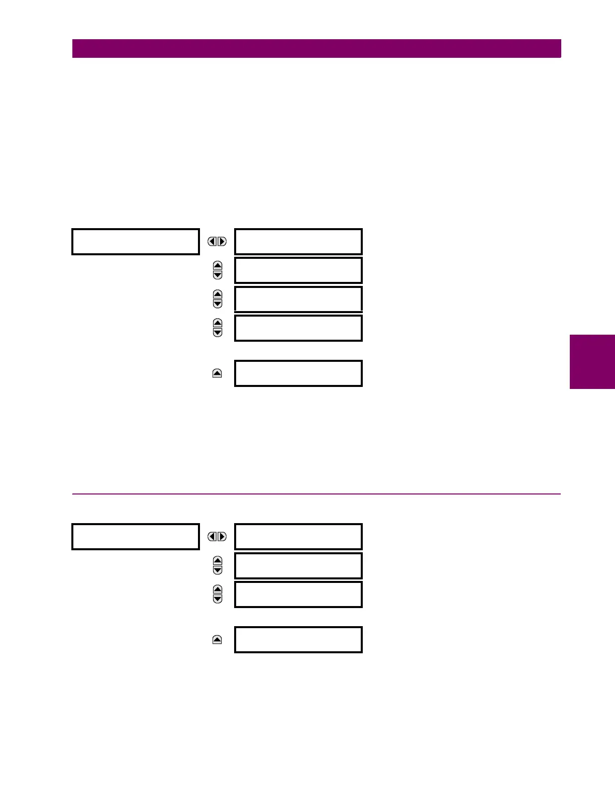
m) ETHERNET SWITCH
PATH: SETTINGS PRODUCT SETUP COMMUNICATIONS ETHERNET SWITCH
These settings appear only if the G60 is ordered with an Ethernet switch module (type 2S or 2T).
The IP address and Modbus TCP port number for the Ethernet switch module are specified in this menu. These settings
are used in advanced network configurations. Please consult the network administrator before making changes to these
settings. The client software (EnerVista UR Setup, for example) is the preferred interface to configure these settings.
The PORT 1 EVENTS through PORT 6 EVENTS settings allow Ethernet switch module events to be logged in the event
recorder.
5.2.5 MODBUS USER MAP
PATH: SETTINGS PRODUCT SETUP MODBUS USER MAP
The Modbus user map provides read-only access for up to 256 registers. To obtain a memory map value, enter the desired
address in the
ADDRESS line (this value must be converted from hex to decimal format). The corresponding value is dis-
played in the
VALUE line. A value of “0” in subsequent register ADDRESS lines automatically returns values for the previous
ADDRESS lines incremented by “1”. An address value of “0” in the initial register means “none” and values of “0” will be dis-
played for all registers. Different
ADDRESS values can be entered as required in any of the register positions.
ETHERNET SWITCH
SWITCH IP ADDRESS:
127.0.0.1
Range: standard IP address format
MESSAGE
SWITCH MODBUS TCP
PORT NUMBER: 502
Range: 1 to 65535 in steps of 1
MESSAGE
PORT 1 EVENTS:
Disabled
Range: Enabled, Disabled
MESSAGE
PORT 2 EVENTS:
Disabled
Range: Enabled, Disabled
MESSAGE
PORT 6 EVENTS:
Disabled
Range: Enabled, Disabled
MODBUS USER MAP
ADDRESS 1: 0
VALUE: 0
Range: 0 to 65535 in steps of 1
MESSAGE
ADDRESS 2: 0
VALUE: 0
Range: 0 to 65535 in steps of 1
MESSAGE
ADDRESS 3: 0
VALUE: 0
Range: 0 to 65535 in steps of 1
MESSAGE
ADDRESS 256: 0
VALUE: 0
Range: 0 to 65535 in steps of 1