GE Multilin G60 Generator Protection System 5-183
5 SETTINGS 5.6 GROUPED ELEMENTS
5
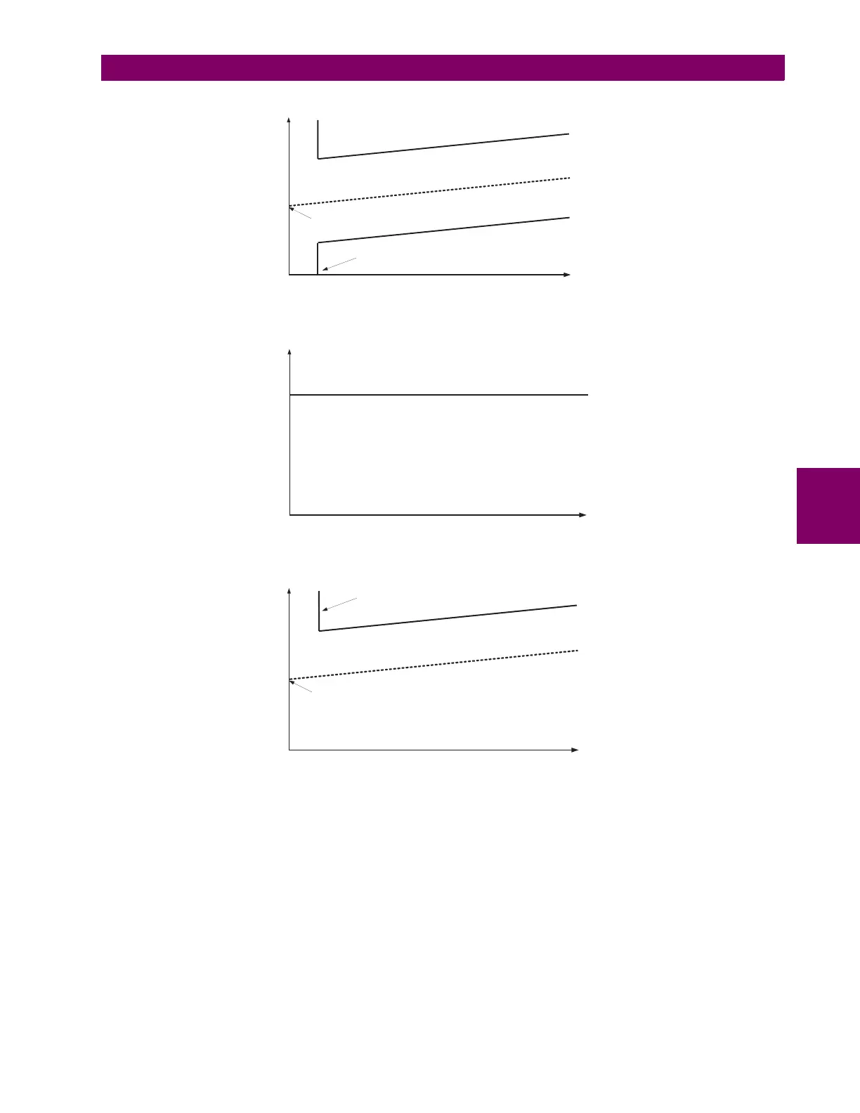
Figure 5–93: SPLIT PHASE PROTECTION OPERATING CHARACTERISTICS
• SPLIT PHASE SOURCE: This setting specifies a signal source used to provide current from the split phase CT to the
split phase protection.
• SPLIT PHASE LOAD SOURCE: This setting specifies a signal source used to provide current from the load CT to the
split phase protection.
• SPLIT PHASE A(C) PICKUP: This setting specifies a pickup level for each phase. This should be set less than the
minimum expected unbalance (split phase) current due to an inter-turn fault.
• SPLIT PHASE A(C) OFFSET: This setting specifies the steady-state split phase current at no-load for the each phase.
This should be set equal to the split phase current during normal (unfaulted) operation. The user should assign the split
phase current and the load current (positive sequence) to the data logger to identify the optimum value for this setting.
• SPLIT PHASE A(C) SLOPE: This setting specifies the slope of split phase characteristic for each phase. This setting
is used to bias the pickup of the element due to variations in generator loading. The slope is defined as the ratio of the
830729A1.CDR
Iload (pu)
I splt phs (pu)
Offset
S
l
o
p
e
O
p
e
r
a
t
e
O
p
e
r
a
t
e
Min Load
Operating Characteristic
Iload (pu)
I splt phs (pu)
Offset
S
l
o
p
e
O
p
e
r
a
t
e
Min Load
Operating Characteristic (mode = over)
Iload (pu)
I splt phs (pu)
O
perate
Operating Characteristic (mode = over, Min Load = 0, Slope = 0)