5-42 G60 Generator Protection System GE Multilin
5.2 PRODUCT SETUP 5 SETTINGS
5
5.2.8 OSCILLOGRAPHY
a) MAIN MENU
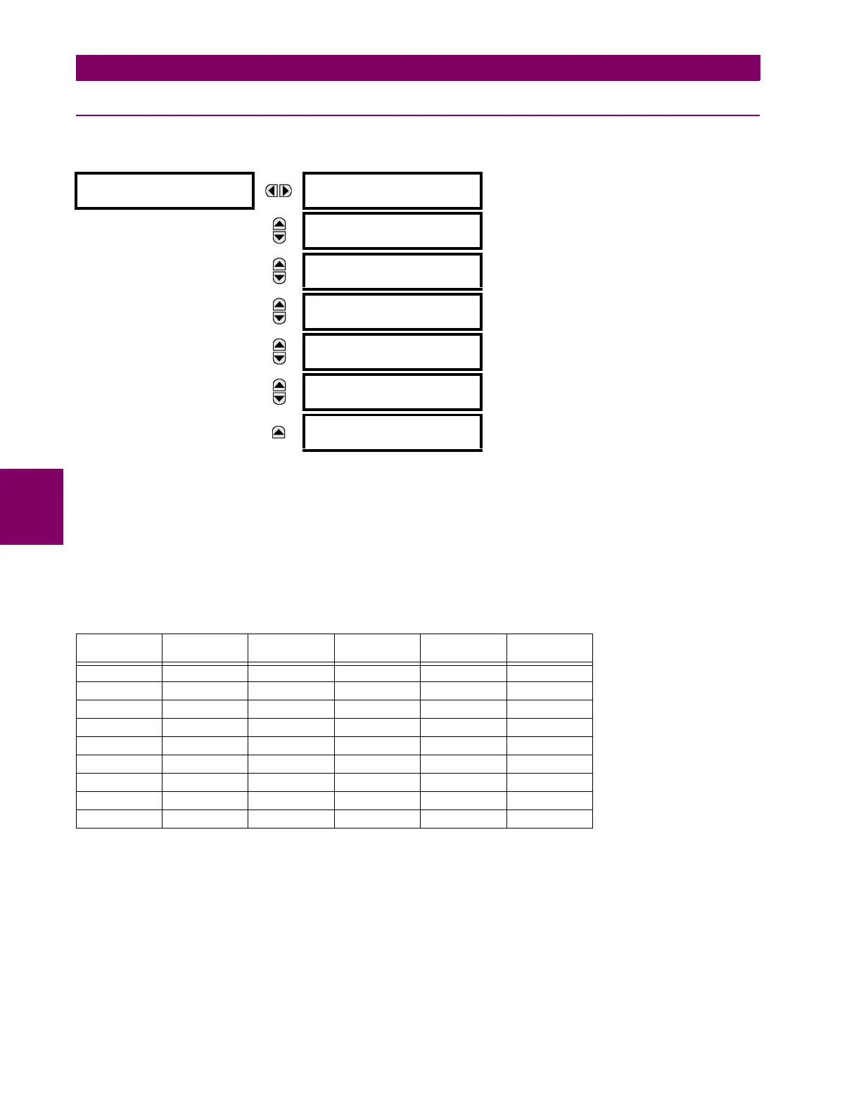
PATH: SETTINGS PRODUCT SETUP OSCILLOGRAPHY
Oscillography records contain waveforms captured at the sampling rate as well as other relay data at the point of trigger.
Oscillography records are triggered by a programmable FlexLogic™ operand. Multiple oscillography records may be cap-
tured simultaneously.
The
NUMBER OF RECORDS is selectable, but the number of cycles captured in a single record varies considerably based on
other factors such as sample rate and the number of operational modules. There is a fixed amount of data storage for oscil-
lography; the more data captured, the less the number of cycles captured per record. See the ACTUAL VALUES
RECORDS OSCILLOGRAPHY menu to view the number of cycles captured per record. The following table provides sam-
ple configurations with corresponding cycles/record.
A new record may automatically overwrite an older record if TRIGGER MODE is set to “Automatic Overwrite”.
Set the TRIGGER POSITION to a percentage of the total buffer size (for example, 10%, 50%, 75%, etc.). A trigger position of
25% consists of 25% pre- and 75% post-trigger data. The TRIGGER SOURCE is always captured in oscillography and may be
any FlexLogic™ parameter (element state, contact input, virtual output, etc.). The relay sampling rate is 64 samples per
cycle.
The
AC INPUT WAVEFORMS setting determines the sampling rate at which AC input signals (that is, current and voltage) are
stored. Reducing the sampling rate allows longer records to be stored. This setting has no effect on the internal sampling
rate of the relay which is always 64 samples per cycle; that is, it has no effect on the fundamental calculations of the device.
OSCILLOGRAPHY
NUMBER OF RECORDS:
5
Range: 1 to 64 in steps of 1
MESSAGE
TRIGGER MODE:
Automatic Overwrite
Range: Automatic Overwrite, Protected
MESSAGE
TRIGGER POSITION:
50%
Range: 0 to 100% in steps of 1
MESSAGE
TRIGGER SOURCE:
Off
Range: FlexLogic™ operand
MESSAGE
AC INPUT WAVEFORMS:
16 samples/cycle
Range: Off; 8, 16, 32, 64 samples/cycle
MESSAGE
DIGITAL CHANNELS
MESSAGE
ANALOG CHANNELS
Table 5–2: OSCILLOGRAPHY CYCLES/RECORD EXAMPLE
RECORDS CT/VTS SAMPLE
RATE
DIGITALS ANALOGS CYCLES/
RECORD
118001872.0
1 1 16 16 0 1685.0
8 1 16 16 0 276.0
8 1 16 16 4 219.5
8 2 16 16 4 93.5
8 2 16 63 16 93.5
8 2 32 63 16 57.6
8 2 64 63 16 32.3
322 6463169.5