10-4 G60 Generator Protection System GE Multilin
10.1 SETTING EXAMPLE 10 APPLICATION OF SETTINGS
10
10.1.7 LOSS OF EXCITATION
For the example system, we have the following values:
(EQ 10.7)
(EQ 10.8)
(EQ 10.9)
(EQ 10.10)
(EQ 10.11)
(EQ 10.12)
(EQ 10.13)
(EQ 10.14)
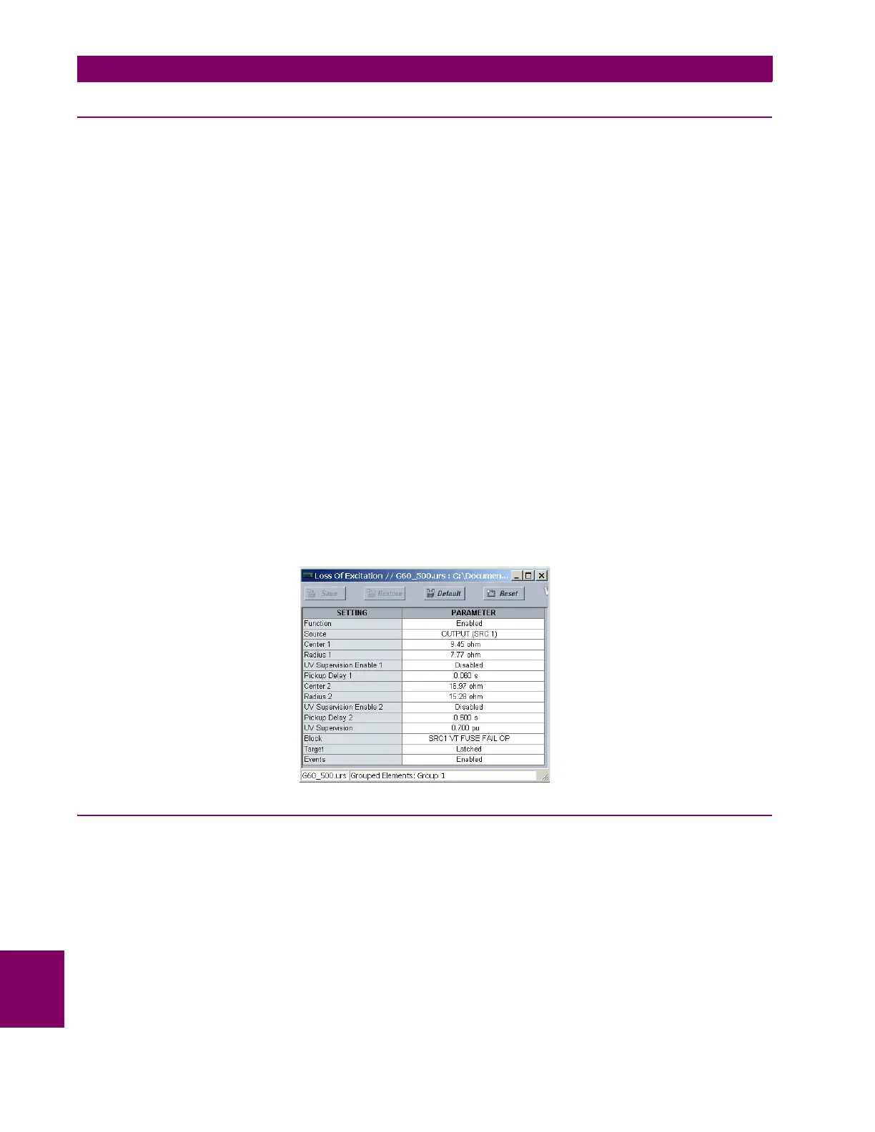
The voltage supervision setting will be determined by a system study and may be disabled on either element if required. VT
fuse failure should supervise this element.
The choice of source is not critical for this application. The NEUTRL source is chosen for the following setting changes.
Make the following changes in EnerVista UR Setup or through the
SETTINGS GROUPED ELEMENTS SETTING GROUP
1 LOSS OF EXCITATION menu:
10.1.8 REVERSE POWER
The reverse power element should be set at ½ the rated motoring power. The pickup is calculated as follows:
(EQ 10.15)
For the example system:
Z
b sec
base kV
2
base MVA
---------------------------
CT ratio
VT ratio
---------------------
18 kV
2
211.765 MVA
------------------------------------
1600
157.5
-------------- -
15.54 == =
X
d
(sec) X
d
Z
b
(sec) 0.216 15.54 3.36 == =
X
d
secX
d
Z
b
sec 1.967 15.54 30.57 == =
CENTER 1
Z
b
secX
d
(sec)+
2
-------------------------------------------------
15.54 3.36+
2
------------------------------------------ - 9.45 ===
RADIUS 1
Z
b
sec
2
--------------------
15.54
2
--------------------- - 7.77 == =
PICKUP DELAY 1 0.06 seconds=
CENTER 2
X
d
secX
d
(sec)+
2
-------------------------------------------------
30.57 3.36+
2
------------------------------------------ - 16.97 ===
RADIUS 2
X
d
sec
2
---------------------
30.57
2
--------------------- - 15.28 == =
S
min
1
2
---
Rated Motoring Power (primary watts)
3 Phase CT Primary Phase VT Ratio Phase VT Secondary
------------------------------------------------------------------------------------------------------------------------------------------------------------------------- -
=
S
min
1
2
---
22 10
6
W
3 8000 A 157.5 66 V
---------------------------------------------------------------------
0.044 pu==