5-264 G60 Generator Protection System GE Multilin
5.8 INPUTS/OUTPUTS 5 SETTINGS
5
The GOOSE analog input FlexAnalog™ values are available for use in other G60 functions that use FlexAnalog™ values.
5.8.13 IEC 61850 GOOSE INTEGERS
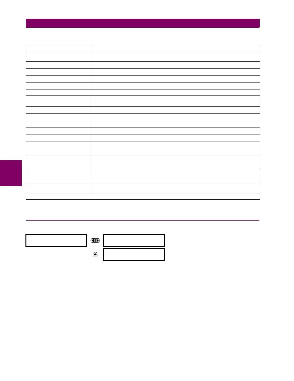
PATH: SETTINGS INPUTS/OUTPUTS IEC 61850 GOOSE UINTEGERS GOOSE UINTEGER INPUT 1(16)
The IEC 61850 GOOSE uinteger inputs feature allows the transmission of FlexInteger™ values between any two UR-
series devices. The following settings are available for each GOOSE uinteger input.
• UINTEGER 1 DEFAULT: This setting specifies the value of the GOOSE uinteger input when the sending device is
offline and the
UINTEGER 1 DEFAULT MODE is set to “Default Value”.This setting is stored as a 32-bit unsigned integer
number.
• UINTEGER 1 DEFAULT MODE: When the sending device is offline and this setting is “Last Known”, the value of the
GOOSE uinteger input remains at the last received value. When the sending device is offline and this setting value is
“Default Value”, then the value of the GOOSE uinteger input is defined by the
UINTEGER 1 DEFAULT setting.
The GOOSE integer input FlexInteger™ values are available for use in other G60 functions that use FlexInteger™ values.
Table 5–33: GOOSE ANALOG INPUT BASE UNITS
ELEMENT BASE UNITS
dcmA BASE = maximum value of the
DCMA INPUT MAX setting for the two transducers configured
under the +IN and –IN inputs.
FREQUENCY f
BASE
= 1 Hz
FREQUENCY RATE OF CHANGE df/dt
BASE
= 1 Hz/s
PHASE ANGLE
BASE
= 360 degrees (see the UR angle referencing convention)
POWER FACTOR PF
BASE
= 1.00
RTDs BASE = 100°C
SENSITIVE DIR POWER
(Sns Dir Power)
P
BASE
= maximum value of 3 V
BASE
I
BASE
for the +IN and –IN inputs of the sources
configured for the sensitive power directional element(s).
SOURCE CURRENT I
BASE
= maximum nominal primary RMS value of the +IN and –IN inputs
SOURCE ENERGY
(Positive and Negative Watthours,
Positive and Negative Varhours)
E
BASE
= 10000 MWh or MVAh, respectively
SOURCE POWER P
BASE
= maximum value of V
BASE
I
BASE
for the +IN and –IN inputs
SOURCE VOLTAGE V
BASE
= maximum nominal primary RMS value of the +IN and –IN inputs
STATOR DIFFERENTIAL
CURRENT
(Stator Diff Iar, Ibr, and Icr)
I
BASE
= maximum primary RMS value of the +IN and –IN inputs
(CT primary for source currents, and bus reference primary current for bus differential currents)
STATOR GROUND 3RD
HARMONIC VOLTAGES
(Stator Gnd Vn/V0 3rd)
V
BASE
= Primary auxiliary voltage of the STATOR GROUND SOURCE
STATOR RESTRAINING
CURRENT
(Stator Diff Iad, Ibd, and Icd)
I
BASE
= maximum primary RMS value of the +IN and –IN inputs
(CT primary for source currents, and bus reference primary current for bus differential currents)
SYNCHROCHECK
(Max Delta Volts)
V
BASE
= maximum primary RMS value of all the sources related to the +IN and –IN inputs
VOLTS PER HERTZ BASE = 1.00 pu
GOOSE UINTEGER
INPUT 1
UINTEGER 1 DEFAULT:
1000
Range: 0 to 429496295 in steps of 1
MESSAGE
UINTEGER 1 DEFAULT
MODE: Default Value
Range: Default Value, Last Known