GE Multilin G60 Generator Protection System 5-89
5 SETTINGS 5.4 SYSTEM SETUP
5
5.4.7 PHASOR MEASUREMENT UNIT
a) MAIN MENU
PATH: SETTINGS SYSTEM SETUP PHASOR MEASUREMENT UNIT
The G60 Generator Protection System is provided with an optional phasor measurement unit feature. This
feature is specified as a software option at the time of ordering. The number of phasor measurement units
available is also dependent on this option. Refer to the Ordering section of chapter 2 for additional details.
UR Synchrophasor Implementation
PHASORS are used within protection relays. If these phasors are referenced to a common time base they are referred to as
a SYNCHROPHASOR. A vastly improved method for tracking power system dynamic phenomena for improved power system
monitoring, protection, operation, and control can be realized if Synchrophasors from different locations within the power
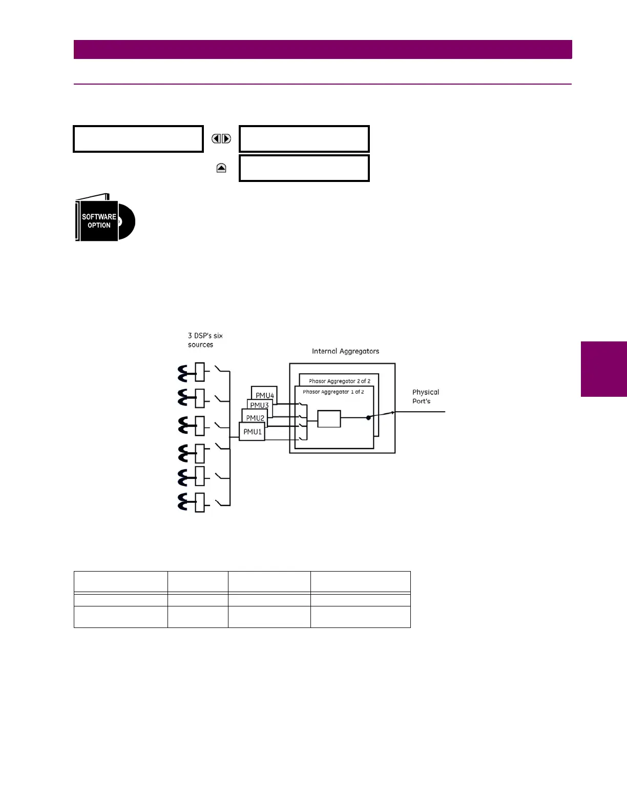
system are networked to a central location. The complete Synchrophasor implementation for Firmware version 6.0 is
shown in the figure below.
Figure 5–34: COMPLETE SYNCHROPHASOR IMPLEMENTATION
The specifics of implementation by model number is summarized in the table below.
Depending on the applied filter, the Synchrophasors that are produced are classified as either P (protection) or M (meter-
ing) class Synchrophasors as described in the latest C37.118 standard. Sychrophasors available within the UR that have
no filtering applied are classified as NONE. Depending on the model number, the UR can support up to a maximum of three
DSP’s. The four PMUs within the UR can be configured to read the sychrophasors from any of the six sources at a user
programmable rate. When one source is selected by one PMU it cannot be used in other PMUs. In firmware version 6.0 a
maximum of two aggregators allow the user to aggregate selected PMUs as per IEC 37.118 to form a custom data set that
is sent to a client optimizing bandwidth. As with sources, a given aggregator can aggregate data form PMUs with the same
rate. With firmware 6.0 a maximum of two PMUs can be set to a reporting rate of 120 Hz for a 60 Hz system (or 100Hz for
PHASOR MEASUREMENT
UNIT
PHASOR MEASUREMENT
UNIT 1
See below.
MESSAGE
REPORTING OVER
NETWORK
See page 5-105.
Table 5–7: IMPLEMENTATION BY MODEL NUMBER
MODEL NUMBER OF
PMUS
NUMBER OF
AGGREGATORS
NUMBER OF ANALOG
INPUTS
N60 4 2 16
D60, F60, G60, L30,
L90, T60
11 16