5-182 G60 Generator Protection System GE Multilin
5.6 GROUPED ELEMENTS 5 SETTINGS
5
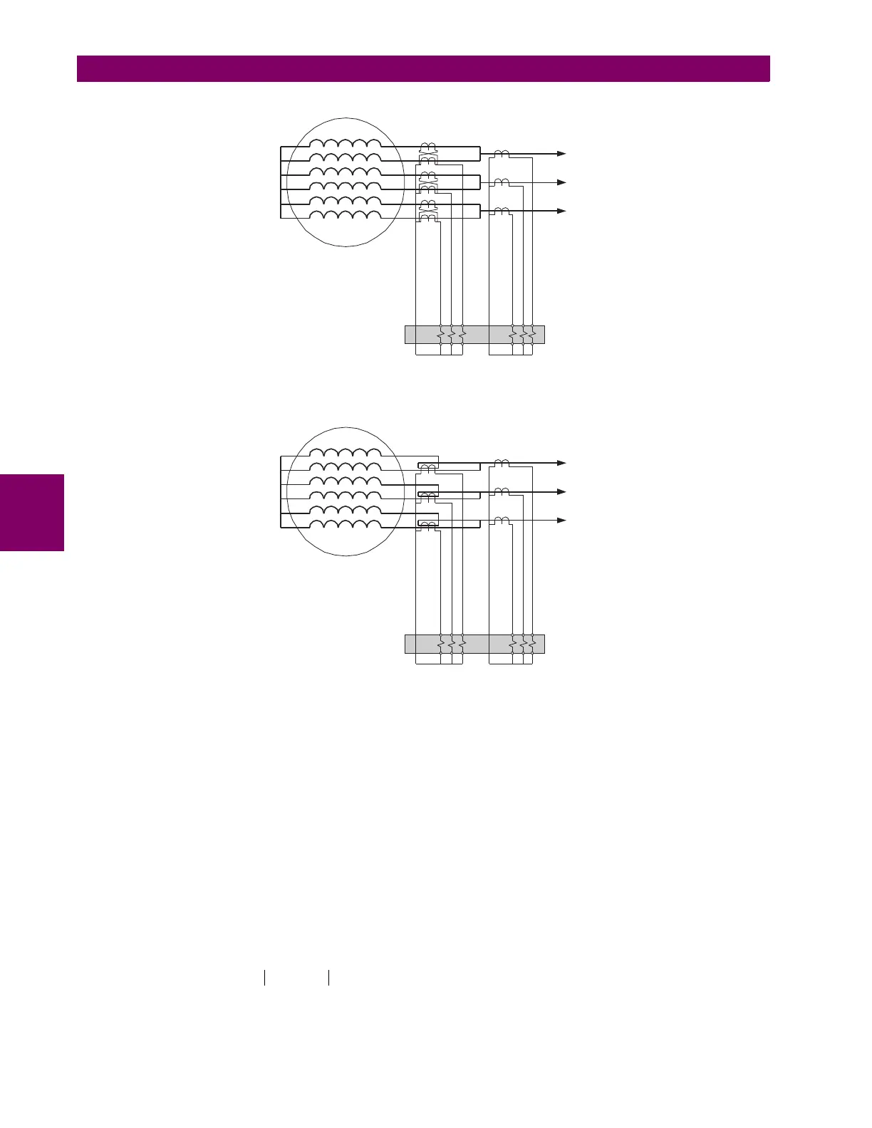
Figure 5–91: SPLIT PHASE PROTECTION FOR 2 CTS
Figure 5–92: SPLIT PHASE PROTECTION FOR 1 CT
The split phase element principle of operation is as follows. First, define the following parameters:
I
split
: split-phase current, I
load
: load current, pickup: pickup setting, min_load: minimum load supervision setting
Then, the expected value of the steady state unbalance (defined as bias current) is expressed as follows:
(EQ 5.24)
where:
(EQ 5.25)
and offset is the split phase current at no-load. In “Over” mode, the element will pickup if:
(EQ 5.26)
In “Over-under”, mode, the element will pickup if:
(EQ 5.27)
830728A1.CDR
Split Phase
Source
Load
Source
830727A1.CDR
Split Phase
Source
Load
Source
I
bias
slope I
load
offset+=
slope
I
split
I
load
-----------
Load CT Primary
Load CT Secondary
-----------------------------------------------------
Split Phase CT Secondary
Split Phase CT Primary
----------------------------------------------------------------------
=
I
split
I
bias
– pickup and I
load
min_load
I
split
I
bias
– pickup and I
load
min_load