GE Multilin G60 Generator Protection System 5-19
5 SETTINGS 5.2 PRODUCT SETUP
5
The G60 supports the Distributed Network Protocol (DNP) version 3.0. The G60 can be used as a DNP slave device con-
nected to multiple DNP masters (usually an RTU or a SCADA master station). Since the G60 maintains two sets of DNP
data change buffers and connection information, two DNP masters can actively communicate with the G60 at one time.
The IEC 60870-5-104 and DNP protocols cannot be simultaneously. When the IEC 60870-5-104 FUNCTION set-
ting is set to “Enabled”, the DNP protocol will not be operational. When this setting is changed it will not
become active until power to the relay has been cycled (off-to-on).
The DNP Channels sub-menu is shown below.
PATH: SETTINGS PRODUCT SETUP COMMUNICATIONS DNP PROTOCOL DNP CHANNELS
The DNP CHANNEL 1 PORT and DNP CHANNEL 2 PORT settings select the communications port assigned to the DNP protocol
for each channel. Once DNP is assigned to a serial port, the Modbus protocol is disabled on that port. Note that COM1 can
be used only in non-Ethernet UR relays. When this setting is set to “Network - TCP”, the DNP protocol can be used over
TCP/IP on channels 1 or 2. When this value is set to “Network - UDP”, the DNP protocol can be used over UDP/IP on chan-
nel 1 only. Refer to Appendix E for additional information on the DNP protocol.
Changes to the
DNP CHANNEL 1 PORT and DNP CHANNEL 2 PORT settings will take effect only after power has
been cycled to the relay.
The DNP NETWORK CLIENT ADDRESS settings can force the G60 to respond to a maximum of five specific DNP masters. The
settings in this sub-menu are shown below.
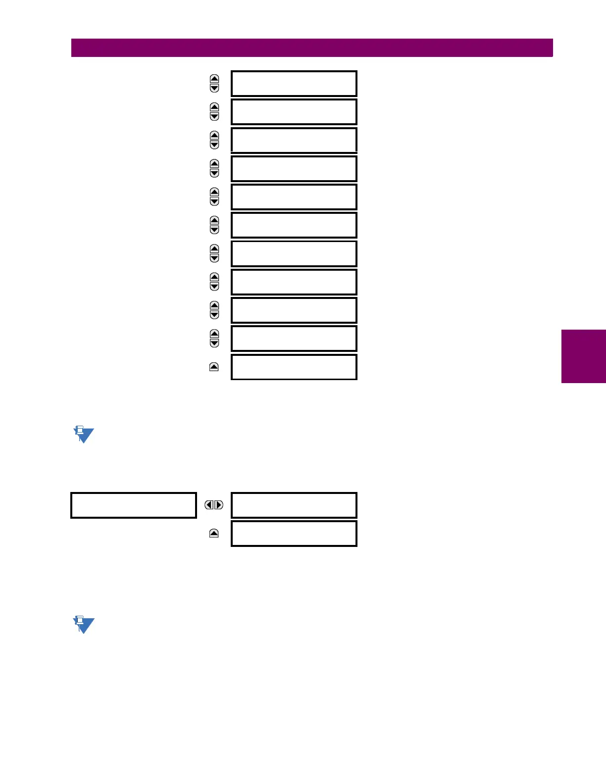
MESSAGE
DNP MESSAGE FRAGMENT
SIZE: 240
Range: 30 to 2048 in steps of 1
MESSAGE
DNP OBJECT 1
DEFAULT VARIATION: 2
Range: 1, 2
MESSAGE
DNP OBJECT 2
DEFAULT VARIATION: 2
Range: 1, 2
MESSAGE
DNP OBJECT 20
DEFAULT VARIATION: 1
Range: 1, 2, 5, 6
MESSAGE
DNP OBJECT 21
DEFAULT VARIATION: 1
Range: 1, 2, 9, 10
MESSAGE
DNP OBJECT 22
DEFAULT VARIATION: 1
Range: 1, 2, 5, 6
MESSAGE
DNP OBJECT 23
DEFAULT VARIATION: 2
Range: 1, 2, 5, 6
MESSAGE
DNP OBJECT 30
DEFAULT VARIATION: 1
Range: 1, 2, 3, 4, 5
MESSAGE
DNP OBJECT 32
DEFAULT VARIATION: 1
Range: 1, 2, 3, 4, 5, 7
MESSAGE
DNP NUMBER OF PAIRED
CONTROL POINTS: 0
Range: 0 to 32 in steps of 1
MESSAGE
DNP TCP CONNECTION
TIMEOUT: 120 s
Range: 10 to 300 s in steps of 1
DNP CHANNELS
DNP CHANNEL 1 PORT:
NETWORK
Range: NONE, COM1 - RS485, COM2 - RS485,
FRONT PANEL - RS232, NETWORK - TCP,
NETWORK - UDP
MESSAGE
DNP CHANNEL 2 PORT:
COM2 - RS485
Range: NONE, COM1 - RS485, COM2 - RS485,
FRONT PANEL - RS232, NETWORK - TCP,
NETWORK - UDP

 Loading...


