GE Multilin G60 Generator Protection System 5-31
5 SETTINGS 5.2 PRODUCT SETUP
5
straint of the MMXU logical node, as per the IEC 61850 standard. According to IEC 61850-7-3, the db value “shall repre-
sent the percentage of difference between the maximum and minimum in units of 0.001%”. Thus, it is important to know the
maximum value for each MMXU measured quantity, since this represents the 100.00% value for the deadband.
The minimum value for all quantities is 0; the maximum values are as follows:
• phase current: 46 phase CT primary setting
• neutral current: 46 ground CT primary setting
• voltage: 275 VT ratio setting
• power (real, reactive, and apparent): 46 phase CT primary setting 275 VT ratio setting
• frequency: 90 Hz
• power factor: 2
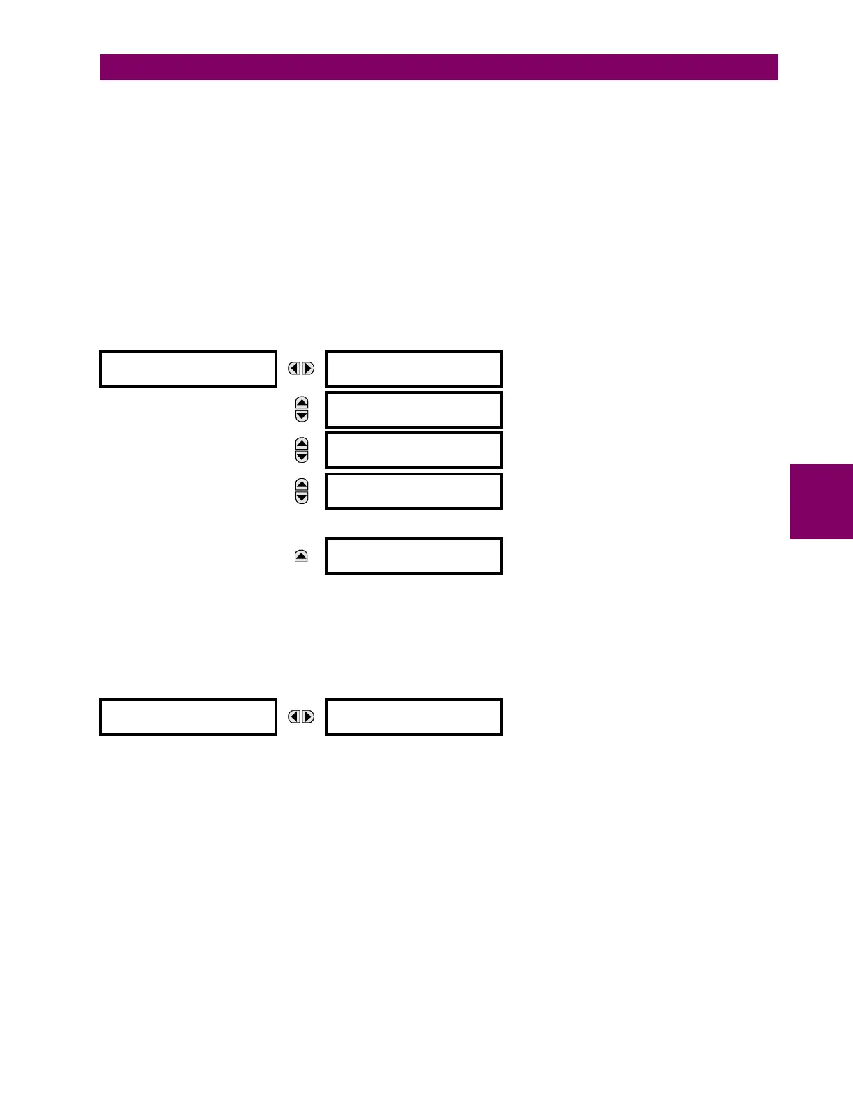
The GGIO1 status configuration points are shown below:
PATH: SETTINGS PRODUCT SETUP COMMUNICATIONS IEC 61850 PROTOCOL GGIO1 STATUS CONFIGURATION
The NUMBER OF STATUS POINTS IN GGIO1 setting specifies the number of “Ind” (single point status indications) that are
instantiated in the GGIO1 logical node. Changes to the NUMBER OF STATUS POINTS IN GGIO1 setting will not take effect until
the G60 is restarted.
The GGIO2 control configuration points are shown below:
PATH: SETTINGS PRODUCT SETUP COMMUNICATIONS IEC 61850 PROTOCOL GGIO2 CONTROL CONFIGURATION
GGIO2 CF SPSCO 1(64)
The GGIO2 control configuration settings are used to set the control model for each input. The available choices are “0”
(status only), “1” (direct control), and “2” (SBO with normal security). The GGIO2 control points are used to control the G60
virtual inputs.
GGIO1 STATUS
CONFIGURATION
NUMBER OF STATUS
POINTS IN GGIO1: 8
Range: 8 to 128 in steps of 8
MESSAGE
GGIO1 INDICATION 1
Off
Range: FlexLogic™ operand
MESSAGE
GGIO1 INDICATION 2
Off
Range: FlexLogic™ operand
MESSAGE
GGIO1 INDICATION 3
Off
Range: FlexLogic™ operand
MESSAGE
GGIO1 INDICATION 128
Off
Range: FlexLogic™ operand
GGIO2 CF SPCSO 1
GGIO2 CF SPCSO 1
CTLMODEL: 1
Range: 0, 1, or 2

 Loading...


