5-50 G60 Generator Protection System GE Multilin
5.2 PRODUCT SETUP 5 SETTINGS
5
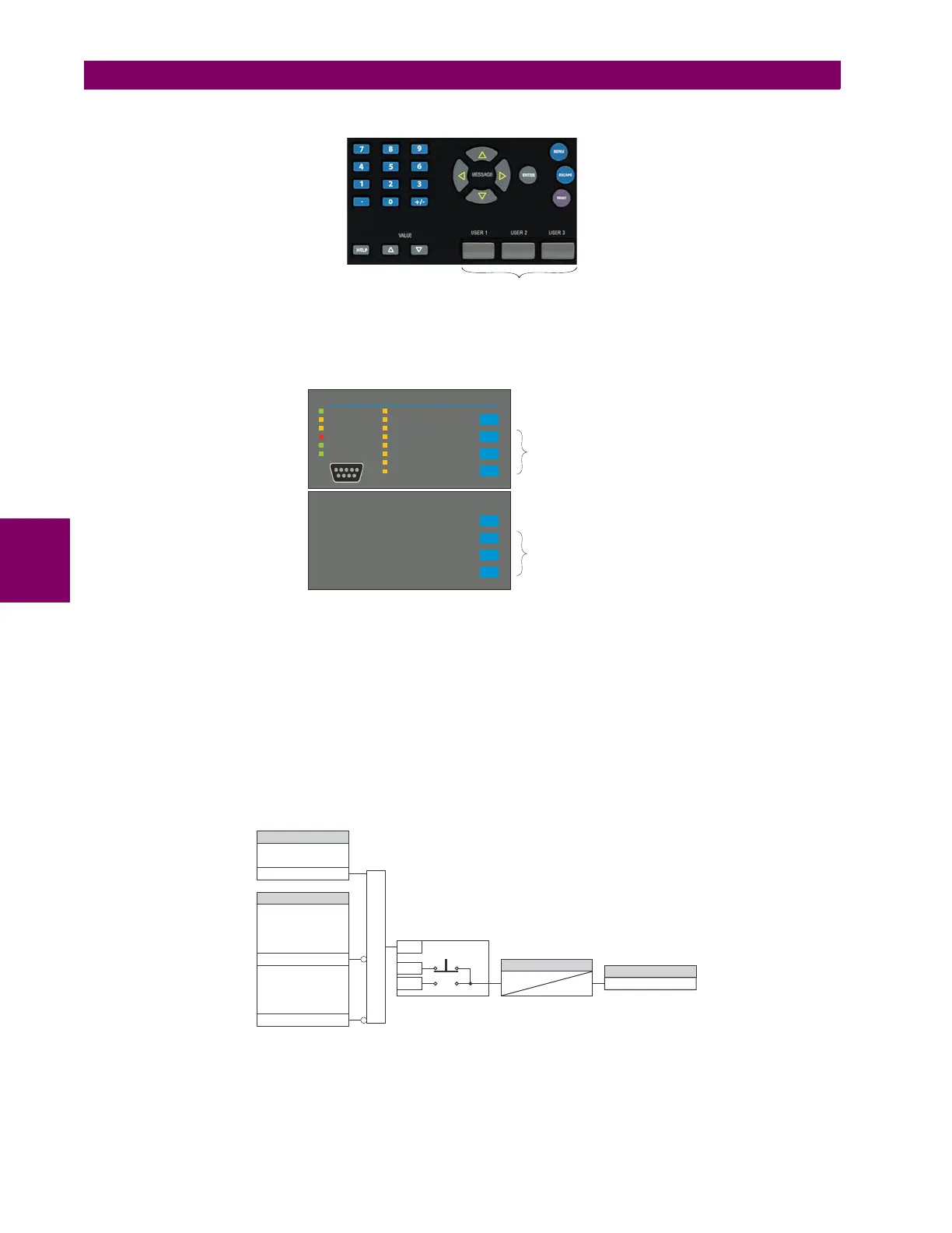
The location of the control pushbuttons are shown in the following figures.
Figure 5–4: CONTROL PUSHBUTTONS (ENHANCED FACEPLATE)
An additional four control pushbuttons are included on the standard faceplate when the G60 is ordered with the twelve
user-programmable pushbutton option.
Figure 5–5: CONTROL PUSHBUTTONS (STANDARD FACEPLATE)
Control pushbuttons are not typically used for critical operations and are not protected by the control password. However,
by supervising their output operands, the user can dynamically enable or disable control pushbuttons for security reasons.
Each control pushbutton asserts its own FlexLogic™ operand. These operands should be configured appropriately to per-
form the desired function. The operand remains asserted as long as the pushbutton is pressed and resets when the push-
button is released. A dropout delay of 100 ms is incorporated to ensure fast pushbutton manipulation will be recognized by
various features that may use control pushbuttons as inputs.
An event is logged in the event record (as per user setting) when a control pushbutton is pressed. No event is logged when
the pushbutton is released. The faceplate keys (including control keys) cannot be operated simultaneously – a given key
must be released before the next one can be pressed.
Figure 5–6: CONTROL PUSHBUTTON LOGIC
Control pushbuttons
842813A1.CDR
842733A2.CDR
PICKUP
ALARM
TRIP
TEST MODE
TROUBLE
IN SERVICE
STATUS
USER 3
USER 2
USER 1
RESET
EVENT CAUSE
NEUTRAL/GROUND
PHASE C
PHASE B
PHASE A
OTHER
FREQUENCY
CURRENT
VOLTAGE
THREE
STANDARD
CONTROL
PUSHBUTTONS
USER 7
USER 6
USER 5
USER 4
FOUR EXTRA
OPTIONAL
CONTROL
PUSHBUTTONS
842010A2.CDR
CONTROL PUSHBUTTON
1 FUNCTION:
SYSTEM SETUP/
BREAKERS/BREAKER 1/
BREAKER 1 PUSHBUTTON
:CONTROL
SYSTEM SETUP/
BREAKERS/BREAKER 2/
BREAKER 2 PUSHBUTTON
:CONTROL
SETTING
SETTINGS
TIMER
FLEXLOGIC OPERAND
Enabled=1
Enabled=1
When applicable
Enabled=1
RUN
OFF
ON
AND
100 msec
0
CONTROL PUSHBTN 1 ON
{
 Loading...


