5-74 G60 Generator Protection System GE Multilin
5.4 SYSTEM SETUP 5 SETTINGS
5
EXAMPLE USE OF SOURCES:
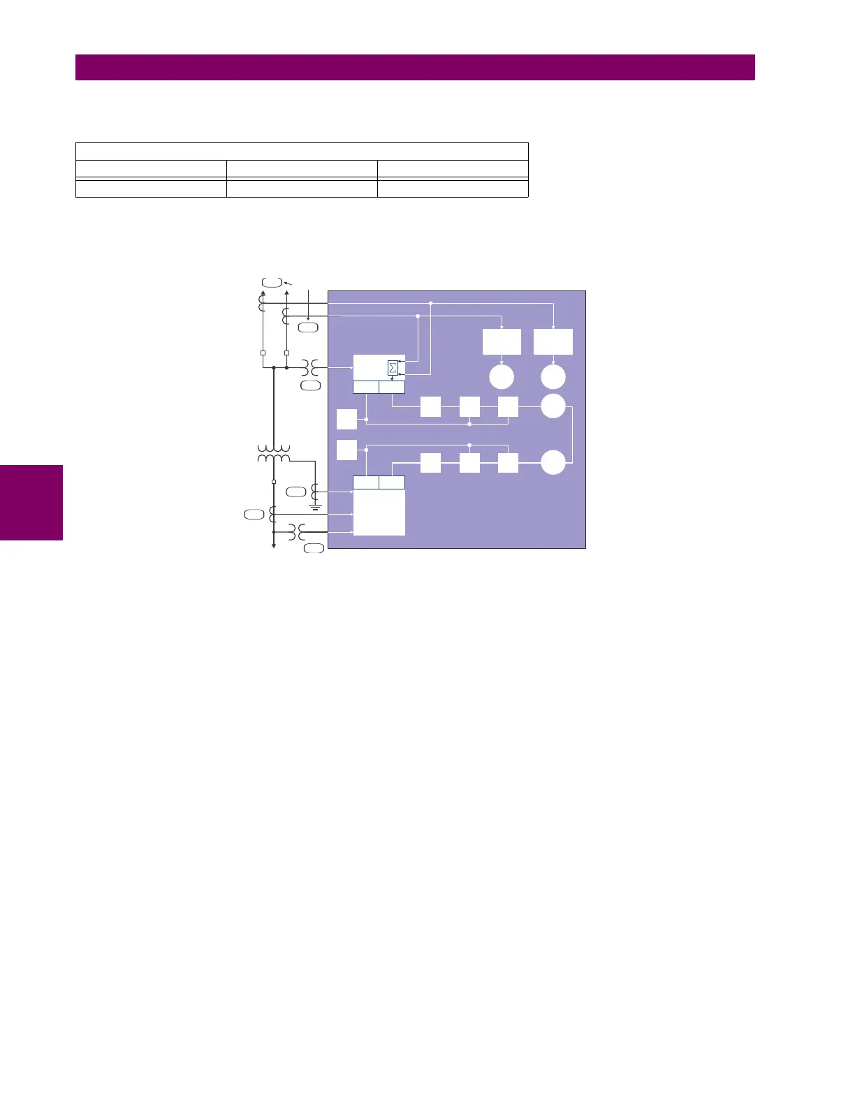
An example of the use of sources is shown in the diagram below. A relay could have the following hardware configuration:
This configuration could be used on a two-winding transformer, with one winding connected into a breaker-and-a-half sys-
tem. The following figure shows the arrangement of sources used to provide the functions required in this application, and
the CT/VT inputs that are used to provide the data.
Figure 5–19: EXAMPLE USE OF SOURCES
INCREASING SLOT POSITION LETTER -->
CT/VT MODULE 1 CT/VT MODULE 2 CT/VT MODULE 3
CTs VTs not applicable
F 5
F 1
DSP Bank
U 1
M 1
M 1
M 5
51BF-1 51BF-2
Source 4
87T
51P
UR Relay
A
V
V
A
W
W
Var
Var
Amps
Source 1
Source 3
Volts
Amps
Amps
Volts
Amps
Source 2

 Loading...


