GE Multilin G60 Generator Protection System 5-101
5 SETTINGS 5.4 SYSTEM SETUP
5
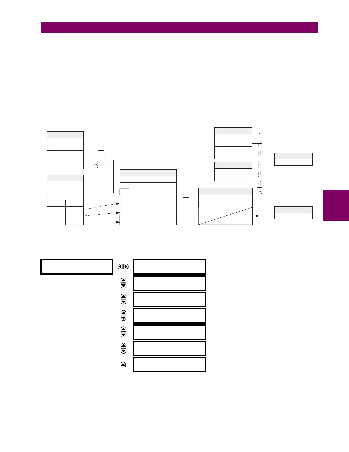
• PMU 1 VOLT TRIGGER LOW-VOLT: This setting specifies the low threshold for the abnormal voltage trigger, in per-
unit of the PMU source. 1 pu is a nominal voltage value defined as the nominal secondary voltage times VT ratio. The
comparator applies a 3% hysteresis.
• PMU 1 VOLT TRIGGER HIGH-VOLT: This setting specifies the high threshold for the abnormal voltage trigger, in per-
unit of the PMU source. 1 pu is a nominal voltage value defined as the nominal secondary voltage times VT ratio. The
comparator applies a 3% hysteresis.
• PMU 1 VOLT TRIGGER PKP TIME: This setting could be used to filter out spurious conditions and avoid unnecessary
triggering of the recorder.
• PMU 1 VOLT TRIGGER DPO TIME: This setting could be used to extend the trigger after the situation returned to nor-
mal. This setting is of particular importance when using the recorder in the forced mode (recording as long as the trig-
gering condition is asserted).
Figure 5–37: VOLTAGE TRIGGER SCHEME LOGIC
i) CURRENT TRIGGERING
PATH: SETTINGS SYSTEM SETUP PHASOR MEASUREMENT... PMU 1 TRIGGERING PMU 1 CURRENT TRIGGER
This element responds to elevated current. The trigger responds to the phase current signal of the phasor measurement
unit (PMU) source. All current channel (A, B, and C) are processed independently and could trigger the recorder.
• PMU 1 CURR TRIGGER PICKUP: This setting specifies the pickup threshold for the overcurrent trigger, in per unit of
the PMU source. A value of 1 pu is a nominal primary current. The comparator applies a 3% hysteresis.
PMU 1 CURRENT
TRIGGER
PMU 1 CURR TRIGGER
FUNCTION: Disabled
Range: Enabled, Disabled
MESSAGE
PMU 1 CURR TRIGGER
PICKUP: 1.800 pu
Range: 0.100 to 30.000 pu in steps of 0.001
MESSAGE
PMU 1 CURR TRIGGER
PKP TIME: 0.10 s
Range: 0.00 to 600.00 s in steps of 0.01
MESSAGE
PMU 1 CURR TRIGGER
DPO TIME: 1.00 s
Range: 0.00 to 600.00 s in steps of 0.01
MESSAGE
PMU 1 CURR TRIG BLK:
Off
Range: FlexLogic™ operand
MESSAGE
PMU 1 CURR TRIGGER
TARGET: Self-Reset
Range: Self-Reset, Latched, Disabled
MESSAGE
PMU 1 CURR TRIGGER
EVENTS: Disabled
Range: Enabled, Disabled
847005A1.CDR
SETTINGS
PMU 1 VOLT TRIGGER
FUNCTION:
Enabled = 1
PMU 1 VOLT TRIG BLK:
Off=0
SETTINGS
PMU 1 SIGNAL
SOURCE:
AND
SETTINGS
PMU 1 VOLT TRIGGER LOW-VOLT:
PMU 1 VOLT TRIGGER HIGH-VOLT:
RUN
SETTINGS
PMU 1 VOLT TRIGGER PKP TIME:
PMU 1 VOLT TRIGGER DPO TIME:
t
PKP
t
DPO
FLEXLOGIC OPERAND
PMU 1 VOLT TRIGGER
FLEXLOGIC OPERANDS
PMU 1 FREQ TRIGGER
PMU 1 CURR TRIGGER
PMU 1 POWER TRIGGER
PMU 1 R OCOF TRIGGER
SETTING
PMU 1 USER TRIGGER:
Off=0
OR
FLEXLOGIC OPERAND
PMU 1 TRIGGERED
VT CONNECTION:
WYE DELTA
VA VAB
VB VBC
VC VCA
(0.1pu < V < LOW-VOLT) OR
(V>HIGH-VOLT)
(0.1pu<V<LOW-VOLT) OR
(V > HIGH-VOLT)
(0.1pu<V<LOW-VOLT) OR
(V>HIGH-VOLT)
OR
to STAT bits of
the data frame