5-134 G60 Generator Protection System GE Multilin
5.6 GROUPED ELEMENTS 5 SETTINGS
5
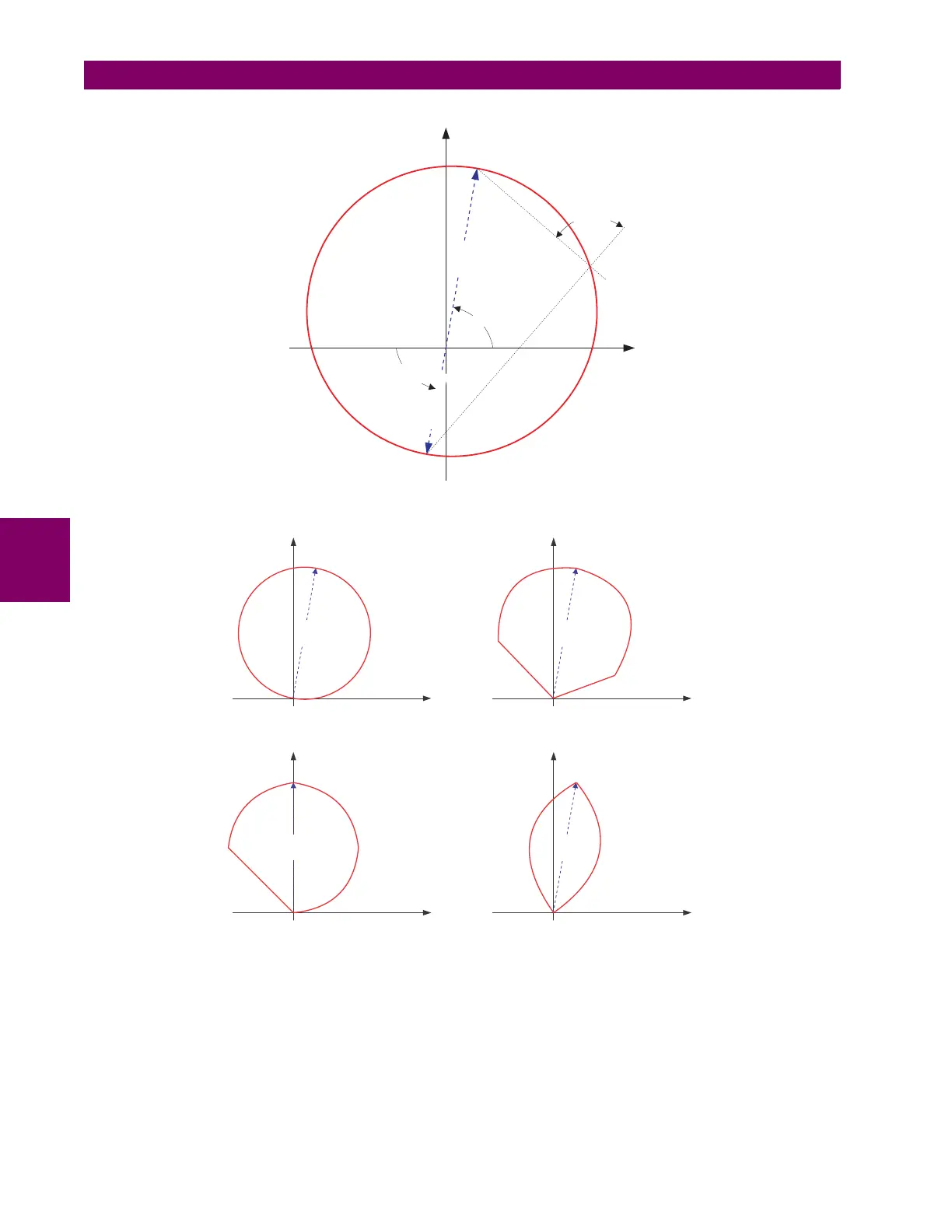
Figure 5–55: NON-DIRECTIONAL MHO DISTANCE CHARACTERISTIC
Figure 5–56: MHO DISTANCE CHARACTERISTIC SAMPLE SHAPES
• PHS DIST Z1 XFMR VOL CONNECTION: The phase distance elements can be applied to look through a three-phase
delta-wye or wye-delta power transformer. In addition, VTs and CTs could be located independently from one another
at different windings of the transformer. If the potential source is located at the correct side of the transformer, this set-
ting shall be set to “None”.
837802A1.CDR
X
R
RCA
COMP LIMIT
REV REACH
REACH
REV REACH
RCA
837722A1.CDR
X
R
REACH
RCA = 80
o
COMP LIMIT = 90
o
DIR RCA = 80
o
DIR COMP LIMIT = 90
o
X
R
REACH
RCA = 80
o
COMP LIMIT = 90
o
DIR RCA = 80
o
DIR COMP LIMIT = 60
o
X
R
REACH
RCA = 80
o
COMP LIMIT = 60
o
DIR RCA = 80
o
DIR COMP LIMIT = 60
o
X
R
REACH
RCA = 90
o
COMP LIMIT = 90
o
DIR RCA = 45
o
DIR COMP LIMIT = 90
o

 Loading...


