5-166 G60 Generator Protection System GE Multilin
5.6 GROUPED ELEMENTS 5 SETTINGS
5
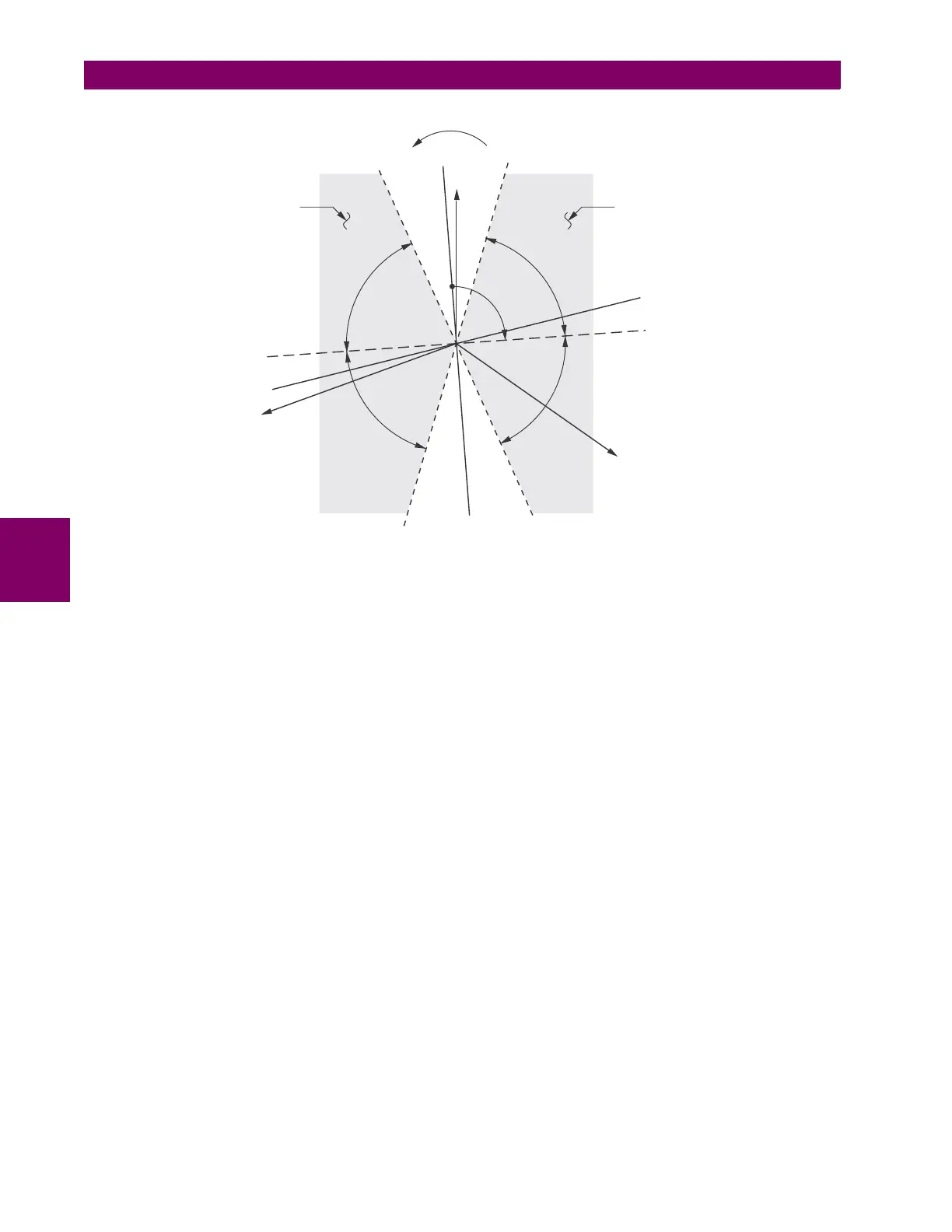
Figure 5–80: NEUTRAL DIRECTIONAL VOLTAGE-POLARIZED CHARACTERISTICS
• NEUTRAL DIR OC1 POLARIZING: This setting selects the polarizing mode for the directional unit.
– If “Voltage” polarizing is selected, the element uses the zero-sequence voltage angle for polarization. The user
can use either the zero-sequence voltage V_0 calculated from the phase voltages, or the zero-sequence voltage
supplied externally as the auxiliary voltage V_X, both from the NEUTRAL DIR OC1 SOURCE.
The calculated V_0 can be used as polarizing voltage only if the voltage transformers are connected in Wye. The
auxiliary voltage can be used as the polarizing voltage provided SYSTEM SETUP AC INPUTS VOLTAGE BANK
AUXILIARY VT CONNECTION is set to “Vn” and the auxiliary voltage is connected to a zero-sequence voltage
source (such as open delta connected secondary of VTs).
The zero-sequence (V_0) or auxiliary voltage (V_X), accordingly, must be greater than 0.02 pu to be validated for
use as a polarizing signal. If the polarizing signal is invalid, neither forward nor reverse indication is given.
– If “Current” polarizing is selected, the element uses the ground current angle connected externally and configured
under
NEUTRAL OC1 SOURCE for polarization. The ground CT must be connected between the ground and neutral
point of an adequate local source of ground current. The ground current must be greater than 0.05 pu to be vali-
dated as a polarizing signal. If the polarizing signal is not valid, neither forward nor reverse indication is given. In
addition, the zero-sequence current (I_0) must be greater than the
PRODUCT SETUP DISPLAY PROPERTIES
CURRENT CUT-OFF LEVEL setting value.
For a choice of current polarizing, it is recommended that the polarizing signal be analyzed to ensure that a known
direction is maintained irrespective of the fault location. For example, if using an autotransformer neutral current
as a polarizing source, it should be ensured that a reversal of the ground current does not occur for a high-side
fault. The low-side system impedance should be assumed minimal when checking for this condition. A similar sit-
uation arises for a wye/delta/wye transformer, where current in one transformer winding neutral may reverse when
faults on both sides of the transformer are considered.
– If “Dual” polarizing is selected, the element performs both directional comparisons as described above. A given
direction is confirmed if either voltage or current comparators indicate so. If a conflicting (simultaneous forward
and reverse) indication occurs, the forward direction overrides the reverse direction.
• NEUTRAL DIR OC1 POL VOLT: Selects the polarizing voltage used by the directional unit when "Voltage" or "Dual"
polarizing mode is set. The polarizing voltage can be programmed to be either the zero-sequence voltage calculated
from the phase voltages ("Calculated V0") or supplied externally as an auxiliary voltage ("Measured VX").
827805A1.CDR
VAG
(reference)
VBG
VCG
–3I_0 line
3I_0 line
ECA line
–ECA line
LA
LA
LA
LA
ECA
FWD LA
line
FWD Operating
Region
REV Operating
Region
FWD LA
line
REV LA
line
REV LA
line
–3V_0 line
3V_0 line