GE Multilin G60 Generator Protection System 5-177
5 SETTINGS 5.6 GROUPED ELEMENTS
5
The element incorporates a current reversal logic: if the reverse direction is indicated for at least 1.25 of a power system
cycle, the prospective forward indication will be delayed by 1.5 of a power system cycle. The element is designed to emu-
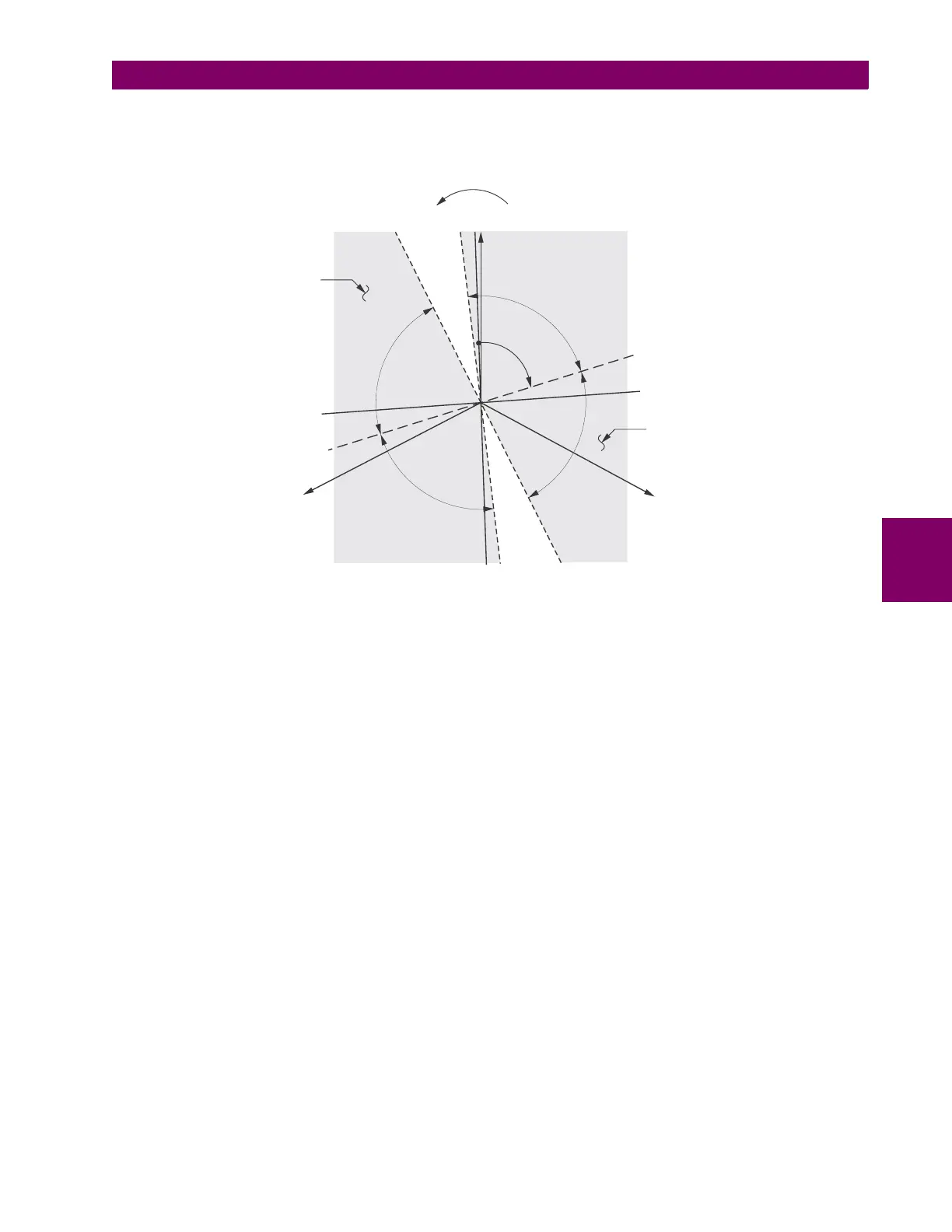
late an electromechanical directional device. Larger operating and polarizing signals will result in faster directional discrimi-
nation bringing more security to the element operation.
Figure 5–87: NEGATIVE-SEQUENCE DIRECTIONAL CHARACTERISTIC
The forward-looking function is designed to be more secure as compared to the reverse-looking function, and therefore
should be used for the tripping direction. The reverse-looking function is designed to be faster as compared to the forward-
looking function and should be used for the blocking direction. This allows for better protection coordination. The above
bias should be taken into account when using the negative-sequence directional overcurrent element to directionalize other
protection elements. The negative-sequence directional pickup must be greater than the
PRODUCT SETUP DISPLAY
PROPERTIES CURRENT CUT-OFF LEVEL setting value.
• NEG SEQ DIR OC1 OFFSET: This setting specifies the offset impedance used by this protection. The primary applica-
tion for the offset impedance is to guarantee correct identification of fault direction on series compensated lines (see
the Application of settings chapter for information on how to calculate this setting). In regular applications, the offset
impedance ensures proper operation even if the negative-sequence voltage at the relaying point is very small. If this is
the intent, the offset impedance shall not be larger than the negative-sequence impedance of the protected circuit.
Practically, it shall be several times smaller. The offset impedance shall be entered in secondary ohms. See the Theory
of operation chapter for additional details.
• NEG SEQ DIR OC1 TYPE: This setting selects the operating mode for the overcurrent unit of the element. The
choices are “Neg Sequence” and “Zero Sequence”. In some applications it is advantageous to use a directional nega-
tive-sequence overcurrent function instead of a directional zero-sequence overcurrent function as inter-circuit mutual
effects are minimized.
• NEG SEQ DIR OC1 POS-SEQ RESTRAINT: This setting controls the positive-sequence restraint. Set to 0.063 (in
“Zero Sequence” mode) or 0.125 (in “Neg Sequence” mode) for backward compatibility with revisions 3.40 and earlier.
Set to zero to remove the restraint. Set higher if large system unbalances or poor CT performance are expected.
• NEG SEQ DIR OC1 FWD ECA: This setting select the element characteristic angle (ECA) for the forward direction.
The element characteristic angle in the reverse direction is the angle set for the forward direction shifted by 180°.
• NEG SEQ DIR OC1 FWD LIMIT ANGLE: This setting defines a symmetrical (in both directions from the ECA) limit
angle for the forward direction.
827806A2.CDR
VAG (reference)
VCG
VBG
–I_2 line
I_2 line
ECA line
–ECA line
LA
LA
LA
LA ECA
FWD Operating
Region
REV Operating
Region
FWD
LA
FWD
LA
REV
LA
REV
LA
V_2 line
–V_2 line
 Loading...


