2-2 G60 Generator Protection System GE Multilin
2.1 INTRODUCTION 2 PRODUCT DESCRIPTION
2
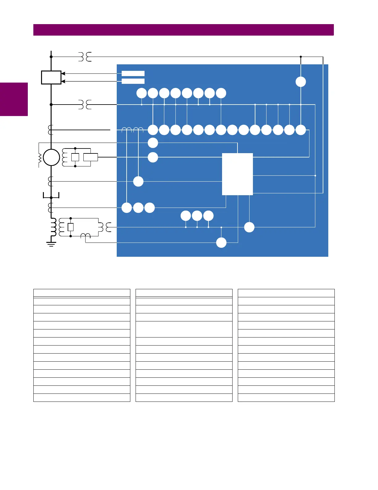
Figure 2–1: SINGLE LINE DIAGRAM
Table 2–2: OTHER DEVICE FUNCTIONS
FUNCTION FUNCTION FUNCTION
Breaker control FlexElements™ (16) Stator differential
Contact inputs (up to 96) Generator unbalance Synchrophasors
Contact outputs (up to 96) IEC 61850 communications (optional) Time synchronization over SNTP
Control pushbuttons Metering: current, voltage, power,
frequency
Transducer inputs and outputs
Data logger Trip output
Digital counters (8) Oscillography User-definable displays
Digital elements (48) Modbus communications User-programmable fault reports
Direct inputs and outputs (32) Modbus user map User-programmable LEDs
Disconnect switches Non-volatile latches User-programmable pushbuttons
DNP 3.0 or IEC 60870-5-104 protocol Non-volatile selector switch User-programmable self-tests
Ethernet Global Data protocol (optional) RTD protection Virtual inputs (64)
Event recorder Remote RTD protection Virtual outputs (96)
FlexLogic™ equations Setting groups (6) VT fuse failure
%&'5
** *
71
3 1
3 1B
3
3
B
0HWHULQJ
7ULS
&ORVH
1
8
2
71
;;
**HQHUDWRU3URWHFWLRQ6\VWHP
5
6
1
5
3
3
*
6
(; *30)
)