5-180 G60 Generator Protection System GE Multilin
5.6 GROUPED ELEMENTS 5 SETTINGS
5
• GEN UNBAL STG1 K-RESET: This setting defines the linear reset rate of the stage 1 element. It is the maximum reset
time from the threshold of tripping. This feature provides a thermal memory of previous unbalance conditions.
• GEN UNBAL STG2 PICKUP: This setting defines the pickup of the stage 2 element expressed as a percentage of the
nominal current as specified by GEN UNBAL INOM setting. The definite time element would normally be used to generate
an alarm to prompt an operator to take some corrective action. The stage 2 element would typically be set at a safe
margin below the stage 1 pickup setting.
• GEN UNBAL STG2 PKP DELAY: This is the minimum operate time of the stage 2 element. This is set to prevent nui-
sance alarms during system faults.
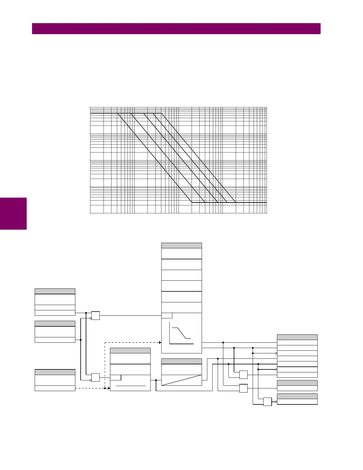
Figure 5–89: GENERATOR UNBALANCE INVERSE TIME CURVES
Figure 5–90: GENERATOR UNBALANCE SCHEME LOGIC
0.1
1
10
100
1000
0.01 0.1 1 10 100
830714A1.CDR
Tmax
K=1 K=4 K=15 K=40 K=100
Tmin
6(77,1*
6(77,1*
6(77,1*6
6(77,1*
6(77,1*6
6(77,1*
)/(;/2*,&23(5$1'6
)/(;/2*,&23(5$1'
)/(;/2*,&23(5$1'
*(181%$/
)81&7,21
*(181%$/
%/.
*(181%$/
6285&(
*(181%$/67*3.3
*(181%$/67*'32
*(181%$/67*23
*(181%$/67*3.3
*(181%$/67*'32
*(181%$/67*23
*(181%$/3.3
*(181%$/23
2II
581
581
,B
(QDEOHG
'LVDEOHG
$1'
25
25
25
$1'
*(181%$/
,120
*(181%$/
67*3,&.83
*(181%$/
67*.9$/8(
*(181%$/
67*70,1
*(181%$/
67*70$;
*(181%$/
67*.5(6(7
*(181%$/67*
3.3'(/$<
*(181%$/67*
3,&.83
*(181%$/,120
,B
W
,B!3,&.83[,120
*(181%$/'32
$&'5
7
3.3
 Loading...


