5-240 G60 Generator Protection System GE Multilin
5.7 CONTROL ELEMENTS 5 SETTINGS
5
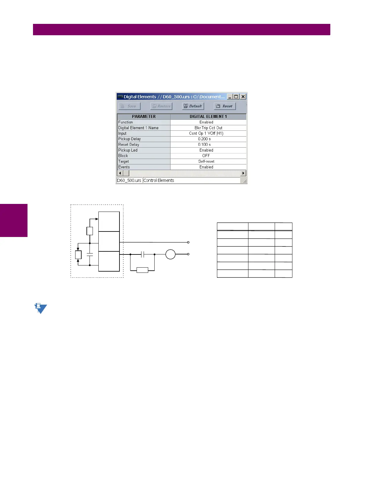
EXAMPLE 2: BREAKER TRIP CIRCUIT INTEGRITY MONITORING
If it is required to monitor the trip circuit continuously, independent of the breaker position (open or closed), a method to
maintain the monitoring current flow through the trip circuit when the breaker is open must be provided (as shown in the fig-
ure below). This can be achieved by connecting a suitable resistor (see figure below) across the auxiliary contact in the trip
circuit. In this case, it is not required to supervise the monitoring circuit with the breaker position – the BLOCK setting is
selected to “Off”. In this case, the settings are as follows (EnerVista UR Setup example shown).
Figure 5–135: TRIP CIRCUIT EXAMPLE 2
The wiring connection for two examples above is applicable to both form-A contacts with voltage monitoring and
solid-state contact with voltage monitoring.
7ULSFRLO
D
85VHULHVGHYLFH
ZLWKIRUP$FRQWDFWV
, FXUUHQWPRQLWRU
9 YROWDJHPRQLWRU
'&²
$&'5
+D
+E
+F
,
9
'&
%\SDVV
UHVLVWRU
5
3RZHUVXSSO\ 5HVLVWDQFH 3RZHU
9'& ű :
9'& ű :
9'& ű :
9'& ű :
9'& ű :
9'& ű :
9DOXHVIRUUHVLVWRU´5µ