10-8 G60 Generator Protection System GE Multilin
10.1 SETTING EXAMPLE 10 APPLICATION OF SETTINGS
10
The time delay should be longer than the longest normal clearing time for faults outside the generator zone. If the phase
VTs are wye-connected then this element should also be coordinated with VT secondary fuses to prevent false operations
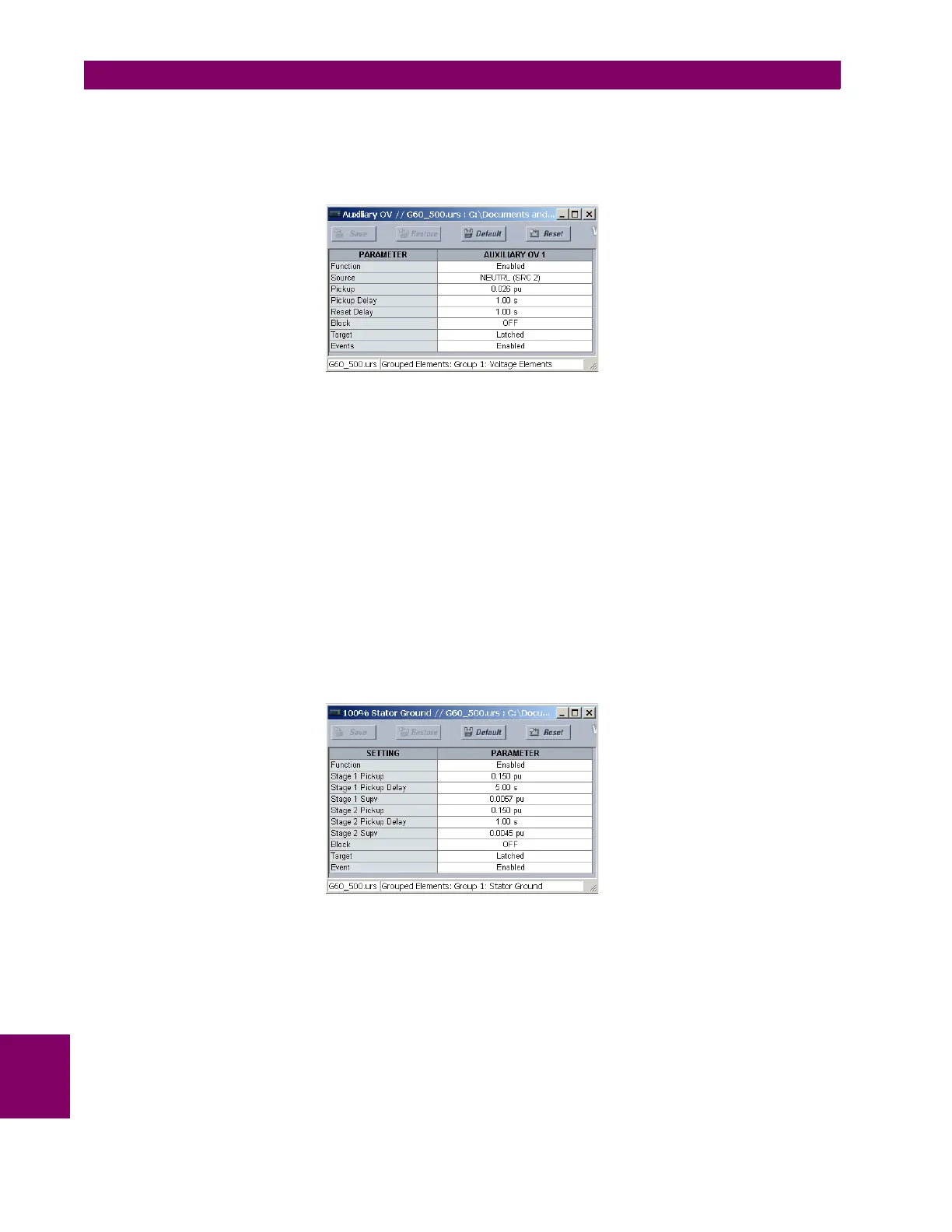
for VT secondary ground faults. For the sample system a time delay of 1 second will be used. Make the following changes
in EnerVista UR Setup or through the
SETTINGS GROUPED ELEMENTS SETTING GROUP 1 VOLTAGE ELEMENTS
AUXILIARY OV1 menu:
b) 100% STATOR GROUND
The auxiliary voltage input is required for both the 100% stator ground and the third harmonic neutral undervoltage ele-
ments. Therefore the NEUTRL source will be assigned for these elements. Make the following changes in the
SETTINGS
GROUPED ELEMENTS SETTING GROUP 1 STATOR GROUND menu
STATOR GROUND SOURCE: "SRC 2" (the "NEUTRL" source)
This 100% stator ground element provides ground fault protection for the neutral end of the stator winding. The element
has two stages. In this application, stage 1 is used to trip the machine and stage 2 is used for alarm purposes. Set the
pickup to 0.15 for both stages to provide adequate overlap with the auxiliary overvoltage element. Set stage 1 to 0.375 V
secondary (this value may be increased for security in particularly noisy environments). Stage 2 is typically set at 0.3 V sec-
ondary. The supervision settings are expressed in per unit of the
NOMINAL PHASE VT SECONDARY setting. The time delay
settings are 5 seconds and 1 second for the Stage 1 and Stage 2 elements respectively.
, (EQ 10.30)
Make the following changes in EnerVista UR Setup or through the SETTINGS GROUPED ELEMENTS SETTING GROUP
1 STATOR GROUND 100% STATOR GROUND menu:
STG1 SUPV
0.375 V
66 V
-------------------- - 0.0057 pu==
STG2 SUPV
0.300 V
66 V
-------------------- - 0.0045 pu==