3 Heat Output
3.1 Equipment Heat Output tables
Refer to Table 4-3. To obtain heat output information for components not specified in Table 4-3,
refer to the appropriate component Pre–Installation Manual listed in Chapter 2, Basic System
Compatibility.
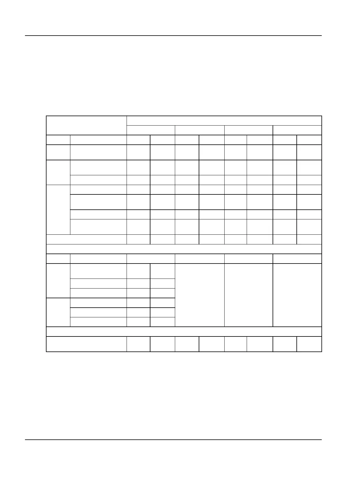
Table 4-3:
HEAT OUTPUT
Stand by Moderate Use (4) Typical Use (4) Maximum Use (4)
Room Core System kW BTU/hr kW BTU/hr kW BTU/hr kW BTU/hr
Exam
Room
LC positioner and table 0.41 1394 0.55 1858 0.89 3020 1.62 5517
Ctrl
Room
DL user area with 1 TFT
monitor
0.16 546 0.16 546 0.16 546 0.16 546
2 B&W flat monitors 0.17 573 0.17 573 0.17 573 0.17 573
Tech
Room
System Control Cabinet 0.70 2387 1.02 3491 1.53 5217 2.16 7378
Coolix X-Ray tube chiller
(1) (2)
2.53 8619 4.49 15309 5.49 18725 6.93 23625
Detector conditioner 0.21 709 0.21 709 0.21 709 0.21 709
Main disconnect panel -
PDB
0.4 1534 0.45 1534 0.45 1534 0.45 1534
Total for core system 4.6 15762 7.0 24020 8.9 30324 11.7 39881
Room Options (3 & 5) Stand by Moderate Use (4) Typical Use (4) Maximum Use (4)
Exam
Room
3 in room B&W TFT mon‐
itors
0.25 859
Same values as
Stand by
Same values as
Stand by
Same values as
Stand by
In room AW TFT monitor 0.12 409
Typical injector 0.09 320
Ctrl
Room
AW work station 0.35 1201
2 AW TFT monitors 0.24 818
Printer 0.31 1054
Typical configuration without fluoro
UPS
5.9 20424 8.4 28682 10.3 34985 13.1 44543
NOTE:
(1) Air flow requirements 1200 m
3
/h (706 CFM)
NOTE: (2) For more details, consult appropriate pre–installation manual
NOTE: (3) For UPS 20 kVA option refer to Section 3.2
NOTE: (4) Moderate use: 8 cases / 10 hours, typical use: 11 cases / 10 hours, maximum use:
during case.
Optima IGS 320, Optima IGS 330 Pre-Installation Manual
Direction 5537562-1-1EN, Revision 3
158 3 Heat Output