1.2.2 Cables to be provided by the installer
For cable # in the folowing tables, refer to Illustration 5-1
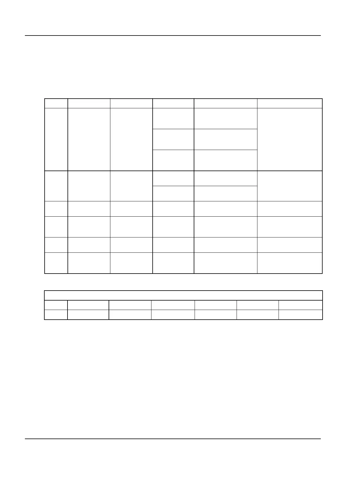
1.2.2.1 Core system
Table 5-3: Core system cables
Cable # From To Type Characteristics Comments
1 Mains PDB
3 phases
Diameter in conformity with
the
Max Line Impedance ta‐
ble
Neutral
Diameter in conformity with
the Max Line Impedance ta‐
ble
Ground
AWG2/35 mm², and not
smaller than the neutral con‐
ductor
2 PDB
Tube Chiller auto
transformer
3 phases
Max length 24 m between
PDB and chiller.
Ground
Min diameter AWG12 (UL) /
4 mm² (CE)
3 PDB
System Control
Cabinet
3 phases
Max length 12m. Min diame‐
ter AWG10 / 5.34 mm²
4 PDB
System Control
Cabinet
3 phases
Max length 12 m. Diameter
in conformity with the Max
Line Impedance below
For the X-ray generator in‐
side Cabinet
5 PDB
System Control
Cabinet
Ground
Max length 12 m. Min diam‐
eter AWG2/35 mm².
7 PDB Injector wall outlet
Phase, neutral
and ground
Max length 24 m. Min diam‐
eter AWG12 (UL) / 1.5 mm²
(CE)
120V outlet UL
Table 5-4:
Max Line Impedance for the line from the Hospital outlet to the X-rays Generator in System Control Cabinet (cables #1 and #4)
V 380 400 415 440 460 480
Ω 0.09 0.096 0.102 0.108 0.114 0.12
Optima IGS 320, Optima IGS 330 Pre-Installation Manual
Direction 5537562-1-1EN, Revision 3
166 1 Power Requirements