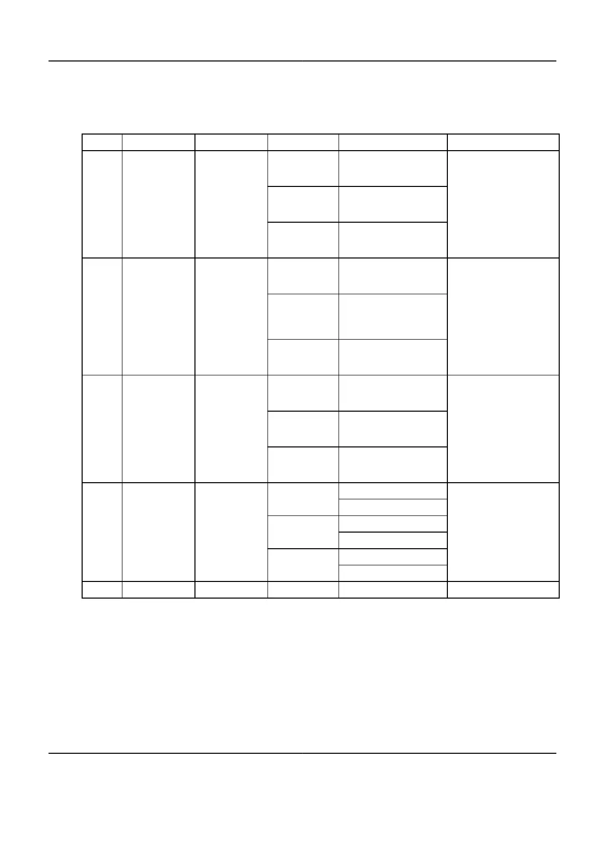
1.2.2.2 For the Fluoro UPS option
Table 5-5: Fluoro UPS option cables
Cable # From To Type Characteristics Comments
1 Mains PDB
3 phases
Diameter in conformity with
the
Max Line Impedance ta‐
ble
Only with UL Fluoro UPS op‐
tion
Neutral
Diameter in conformity with
the Max Line Impedance ta‐
ble
Ground
AWG2/35 mm², and not
smaller than the neutral con‐
ductor
1 Mains EMI Filter
3 phases
Diameter 35 mm² min, in
conformity with the Max Line
Impedance table
Only with CE Fluoro UPS op‐
tion
Neutral
Diameter 35 mm² min, in
conformity with the Max Line
Impedance table (35 mm²
min)
Ground
AWG2/35 mm² and not
smaller than the neutral con‐
ductor
8 EMI Filter PDB
3 phases
Max length 3 m. Diameter in
conformity with the Max Line
Impedance table
Only with CE Fluoro UPSNeutral
Max length 3 m. Diameter in
conformity with the Max Line
Impedance table
Ground
AWG2/35 mm², and not
smaller than the neutral con‐
ductor
9 PDB Fluoro UPS
3 phases
10 mm² (CE)
Max diameter AWG3
AWG6 (UL)
Neutral
10 mm² (CE)
AWG6 (UL)
Ground
10 mm² (CE)
AWG6 (UL)
10 Fluoro UPS PDB 3 phases 10 mm² (CE) Max diameter AWG3
NOTE: Cables 1 and 8 should be routed separately (CE Only) in order to avoid EMC
interference.
1.2.3 LOTO devices provided by the installer
1.2.3.1 Core system
A wall circuit breaker or equivalent device with LOTO capability must be installed on the mains
line to the PBD. This device must be compatible with the power input specifications of the
system. The customer is responsible for the procurement, delivery and installation of this
breaker.
Optima IGS 320, Optima IGS 330 Pre-Installation Manual
Direction 5537562-1-1EN, Revision 3
Chapter 5 Electrical Requirements 167