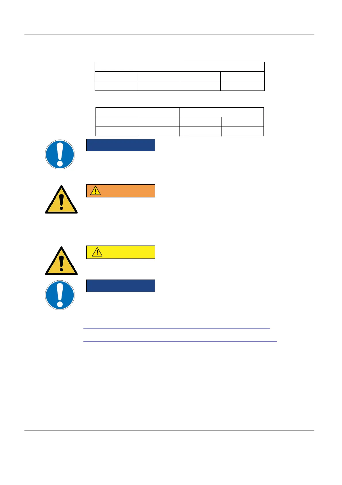
Table 4-4: Fluoro UPS CE
Losses Cooling air flow
VFI SEM VFI SEM
2.14 kW 0.64 kW 625 m
3
/h 190 m
3
/h
Table 4-5: Fluoro UPS UL
Losses Cooling air flow
BTU / hr kW CFM m
3
/h
6751 1.98 301 512
NOTICE
If installed in the technical room, the UPS may impact on it’s layout. It may also
be installed in a separate room. This depends on hospital constraints, local
regulations or EHS rules. Clearance, weight of UPS, airflow and cooling system
should be adapted for the UPS.
WARNING
ELECTRICAL CONTRACTOR IS RESPONSIBLE FOR PROVIDING AND
CONNECTING THE CABLES FROM THE PDB TO THE UPS AND
CONFIGURING THE PDB IN BYPASS MODE. GEHC IS RESPONSIBLE FOR
POWERING ON THE SYSTEM WITH THE UPS IN BYPASS MODE. GEDE IS
RESPONSIBLE FOR UPS COMMISSIONING.
CAUTION
The Fluoro UPS can be installed either in an Electrical Local with restricted
access or in the technical room as per local regulations.
NOTICE
Make sure that local regulations have been applied for the installation of the
Fluoro UPS (dedicated room/fire detection etc.)
NOTE: Refer to the UPS vendor Service Operating Manual for more details:
•
UL Model: UPS Option - Operating Manual SG-UL Series - 20 kVA
•
CE Model: UPS Option - Operating Manual SitePro 20 kVA (series 8)
Optima IGS 320, Optima IGS 330 Pre-Installation Manual
Direction 5537562-1-1EN, Revision 3
160 3 Heat Output
 Loading...


