PROTEUS XR/a
GE MEDICAL SYSTEMS Operator Manual
REV 11 DIRECTION 2259724-100
14-9
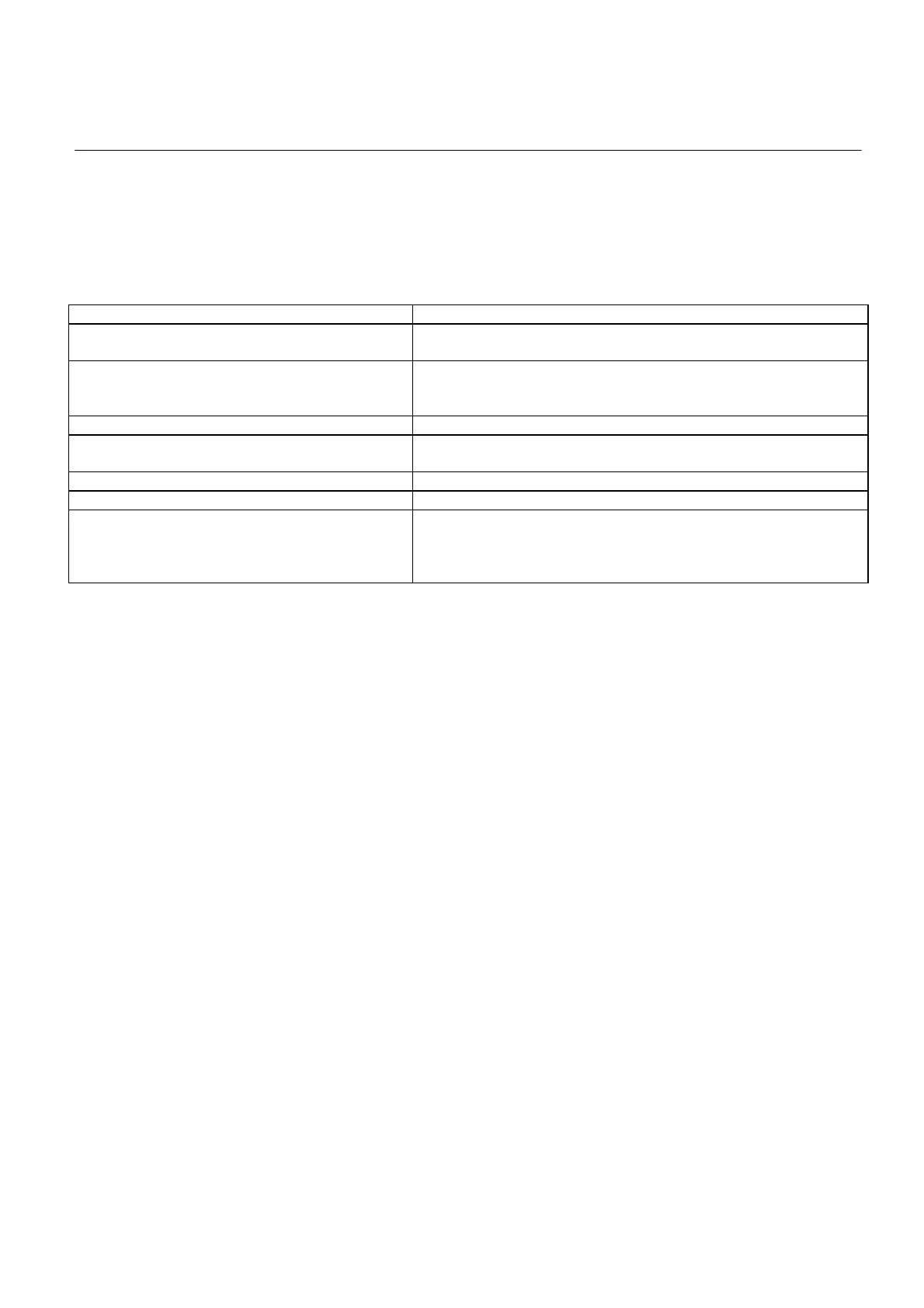
14-3-5 PDU Output Power
See Table 14-18 for PDU output power
TABLE 14-18
PDU OUTPUT POWER
To Wall Stand (GPCP No. 2260354): 31VDC+/-15% 1.5A
To SG120 Wall Stand (GPCP No.: 2402562) 115, 230 V+/- 10% 50/60 Hz
To System IF board: +12VDC 5A
-12VDC 1A
+5VDC 5A
To RAD IF : 230VAC+/-10% 1A 50/60HZ
To table:
220VAC 8A 50/60Hz
240VAC 5A 50/60Hz
To overhead tube suspension: 110VAC+/-10% 5A 50/60Hz
To system console: 12VDC+/-5% 5A
To generator: 380-480VAC 50/60Hz 46kVA@ 32kW
70kVA@ 50kW
97kVA@ 65kW
125kVA@ 80kW
14-3-6 X-ray Interlock Systems
“Deadman’s Switch” X-ray Control Safety System
X-ray emission is terminated instantly when you release the x-ray control
radiography pushbutton.
A special safety circuit uses a signal from second trigger (radiographic
exposure ) controls transmitted directly via relay contacts to the control circuit of
the power inverter. If the microprocessor does not stop x-ray emission after a
delay of several milliseconds, inverter operation is inhibited. In this case, a fault
signal is sent to the control circuits of the generator.
X-ray Tube Housing Overheat Interlock
If the factory-adjusted temperature of the tube housing goes higher than the
permissible level, x-ray emission is terminated.
If it occurs, ask the service Refer to troubleshooting chart.
FOR TRAINING PURPOSES ONLY!
NOTE: Once downloaded, this document is UNCONTROLLED, and therefore may not be the latest revision. Always confirm revision status against a validated source (ie CDL).

 Loading...