3-14 SEER Light Ambulatory Recorder/Controller Revision B
2019818-008
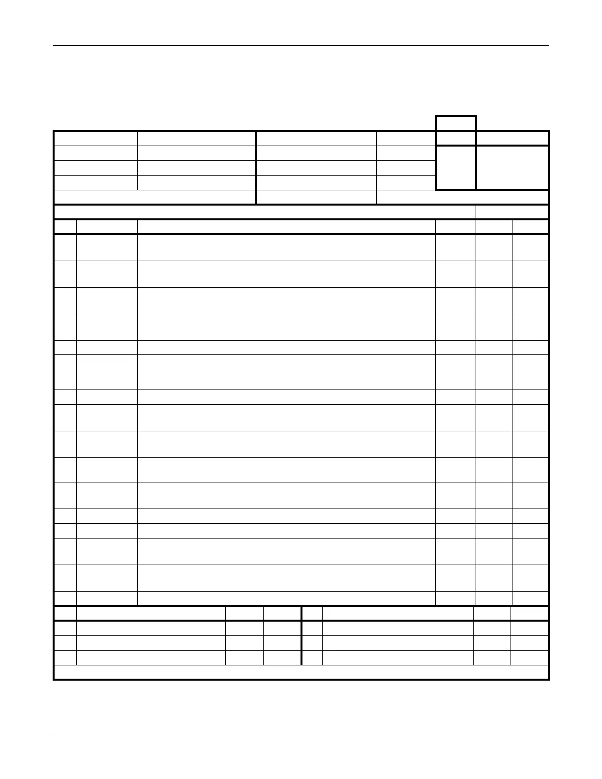
SEER Light/SEER Light Extend Controller: Inspection
Inspection
Production process inspection sheet and inspection procedure.
M. No.
Product Model Name SEER Light Controller Date (Start Inspection) Approval Audit
Serial No. Board No.
Production Lot No.
Program Version Production Specification
High temperature heat run (40 to 48 hours) Start and End Date
Inspection Before Heat-Run Staff
No. Item Inspection Procedures Result Accept Reject
1 Appearance Check paint condition, no scratches or stains on LCD and cases, clear wording,
etc. Check connector pin of memory card for breaks, bends, etc.
2 Power switch Turn ON the power switch. Ensure there are buzzer sounds and the factory reset
menu appears on the LCD. Confirm program version number.
3 Set the time Set year, month, date, and time. Turn off the Auto Power function for heat-run
inspection.
4 Key/LCD check Under the inspection mode, ensure the key input and LCD display are normal,
LCD backlight is lit, and the keys should not stick when pressed.
5 Leakage current Patient leakage current is less than 10 µA. µA
6 Power ON Insert the batteries and confirm buzzer one time. Press start switch, confirm to buzzer and
blink red LED. Then press stop switch and check buzzer sound and LED blinking are
stopped.
7 Start test Ensure that the SEER Light is starting (straight line: 1.5 m).
8 IrDA preview
check
Use SEER Light, which is pre-installed with ECG wave, and ensure that the
displayed waveform of 1 ch, 2 ch, and 3 ch are normal under the preview function.
9 Preview check
with cable
Use SEER Light, which is pre-installed with ECG wave, and ensure that the
displayed analog waveform of 1 ch, 2 ch, and 3 ch are normal.
10 Analog output Using inspection controller with cable, confirm analog waveforms 1 ch, 2 ch, and 3 ch are
normal.
11 Transfer test Connect the SEER Light. Ensure that data is transferred and that the data can be
installed onto the Holter card.
12 Check settings Check the year, month, date, and time (with ±1 minute).
13 Reset menu Used to initialize the settings (menu).
14 Auto Power Off
function
Turn ON the power switch. Check that the power is automatically switched off if no
operation for 15 minutes continuously.
15 Appearance Check painting conditions such as no scratches stains on LCD cases, clear wording,
etc. Check serial plate and battery mark seal (version number) is securely affixed.
Ver. No.
16 Supply current Start at 6 V. The supply current is 60 ±6 mA. mA
No. Visual Inspection Accept Reject No. Visual Inspection Accept Reject
1 Battery mark 1 place 4 Electrode welding 2 places
2 Ribbon 1 place 5 LCD boards, connector cutting 1 place
3 Board installation 1 place 6 Main body assembly 4 places
Notes:
 Loading...


