Revision B SEER Light Ambulatory Recorder/Controller 2-3
2019818-008
SEER Light/SEER Light Extend Recorder: Component Names and Locations
Component Names and Locations
Structure
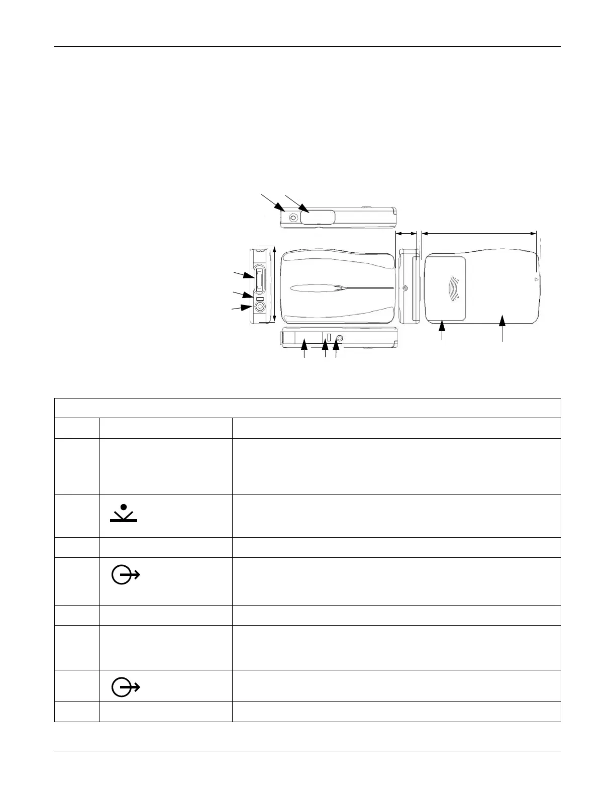
The SEER Light ambulatory recorder is shown and described below.
017A
A B
F E D
I
H
G
.60 in.
(15 mm)
3.35 in.
(85 mm)
2.17 in.(55 mm)
C
J
Table 3. SEER Light Ambulatory Recorder
Item Name Description
A REC LED To display operation conditions:
After pressing the start/event button, the LED will flash twice per second for three
minutes. During this time data is not recorded.
During recording, the LED will flash every second.
B
start/event button
Use to start recording.
Use to mark events during recording.
C battery compartment cover Slide the cover to open and set the batteries in the battery compartment.
D
A data output
connector
For transfer of data to the SEER Light controller or to the SEER Light Connect device.
E access LED Will flash during communication with the SEER Light controller.
F infrared terminal (I.R. Window) Used to receive the signal from the SEER Light controller to begin ECG recording.
Used to receive patient information and ECG recording starting time.
Used to confirm the ECG waveform recorded by the recorder (ECG preview).
G
B output connector
Not used.
H DATA LED The LED flashes while transferring data to the SEER Light controller.