58 V7768/V7769 Hardware Reference Manual
.
A • Appendix A: Connector Pinouts
The V7768/V7769 have several connectors for their I/O ports. Wherever possible,
the V7768/V7769 use connectors and pinouts typical for any desktop PC. This
ensures maximum compatibility with a variety of systems.
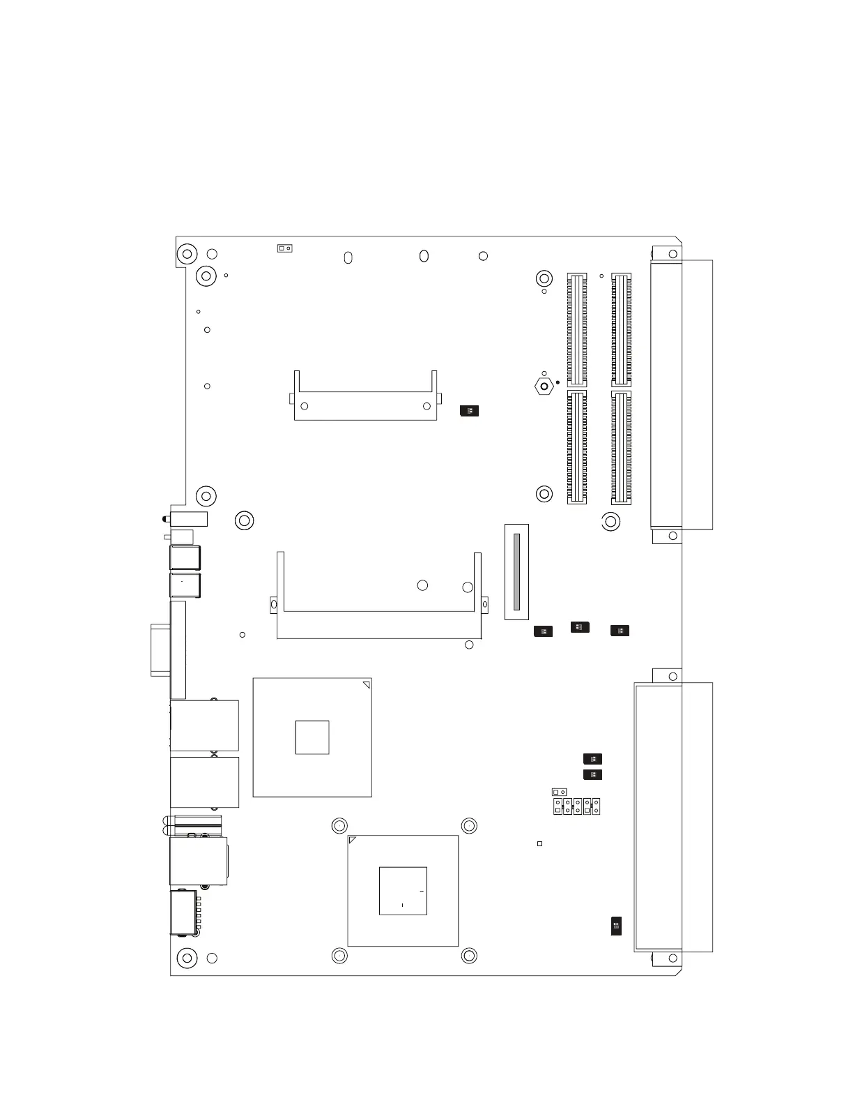
Figure A-1 shows the layout of the connectors on the V7768.
Figure A-1 V7768 Connector Layout
CompactFlash
M/K
USB
USB
P2
P1
P7
J34
SODIMM
ON
1 2
J11
J13
J12
J14
J29
J30
SVGA
J28
COM1
J35
J38
GbE
J15
GbE
J18
J37
(used for V7769 version)
E14
E13
E17
13
5
13
INDICATES PIN 1
ON
1 2
ON
1 2
ON
1 2
ON
1 2
ON
1 2
ON
1 2
S7
S8
S6
S12
S10
S11
S9