10.9 Timer and Counter Functions
This section describes the timing and counting functions of the Instruction Set. The data
associated with these functions is retentive through power cycles.
• On-delay Stopwatch Timer
• Off-delay Timer
• On-delay Timer
• Up Counter
• Down Counter
Time-tick Contacts
In addition to the Timer functions of the Instruction Set, the VersaMax PLC has four
time-tick contacts. These contacts can be used to provide regular pulses of power flow to
other program functions. The four time-tick contacts have time durations of 0.01 second,
0.1 second, 1.0 second, and 1 minute.
The state of these contacts does not change during the execution of the sweep. These
contacts provide a pulse having an equal on and off time duration.
The contacts are referenced as T_10MS (0.01 second), T_100MS (0.1 second), T_SEC
(1.0 second), and T_MIN (1 minute).
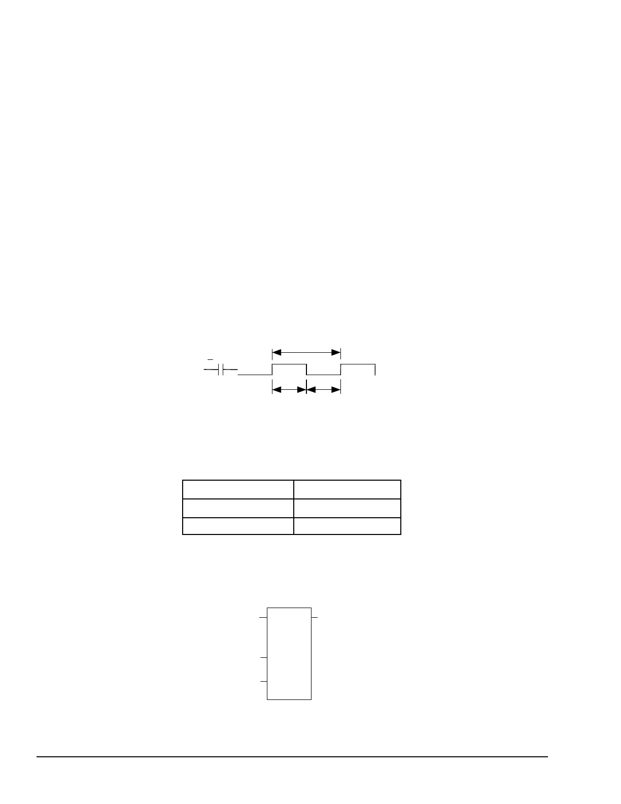
The following timing diagram represents the on/off time duration of these contacts.
These time-tick contacts represent specific locations in %S memory.
Function Block Data Required for Timers and Counters
Each timer or counter uses three words (registers) of %R memory to store the following
information:
current value (CV)
word 1
preset value (PV)
word 2
control word word 3
When you enter a timer or counter, you must enter a beginning address for these three
words (registers). Do not use consecutive registers for the 3 word timer/counter blocks.
Timers and counters will not work if you place the current value of a block on top of the
preset for the previous block.
184 GFK-1503E VersaMax PLC User Manual
For public disclosure

 Loading...


