14.6.3 Ideal Tuning Method
The Ideal Tuning procedure provides the best response to SP changes that are delayed
only by the Tp process delay or dead time.
1. Determine the three process model parameters, K, Tp and Tc for use in estimating
initial PID loop gains.
2. Calculate Kp, Ki, and Kd as follows:
Kp = 2 * Tc/(3 * K * Tp)
Ki = Tc
Kd = Ki/4 if Derivative term is used
3. Once initial gains are determined, convert them to integers.
4. Calculate the Process gain, K, as a change in input PV Counts divided by the
resulting output step change in CV Counts. (Not in process PV or CV engineering
units.) Specify all times in seconds.
5. Once Kp, Ki and Kd are determined, Kp and Kd are multiplied by 100 while Ki is
multiplied by 1000. The resulting values are entered into the corresponding reference
array word locations.
14.6.4 Example
The following PID example has a sample period of 100 ms, a Kp gain of 4.00 and a Ki
gain of 1.500. The set point is stored in %R0001, the control variable is output in %
AQ0002, and the process variable is returned in %AI0003. CV Upper and CV Lower
Clamps must be set, in this case to 20000 and 4000, and an optional small Dead Band of
+5 and -5 is included. The 40-word reference array starts in %R0100. Normally, user
parameters are set in the reference array, but %M0006 can be set to reinitialize the 14
words starting at %R0102 (word 3) from constants stored in logic (a useful technique).
The block can be switched to Manual mode with %M1 so that the Manual Command, %
R113, can be adjusted. Bits %M4 or %M5 can be used to increase or decrease %R113 and
the PID CV by 1 every 100 ms solution. For faster manual operation, bits %M2 and %M3
can be used to add or subtract the value in %R2 to/from %R113 every CPU sweep. The %
T1 output is on when the PID is OK.
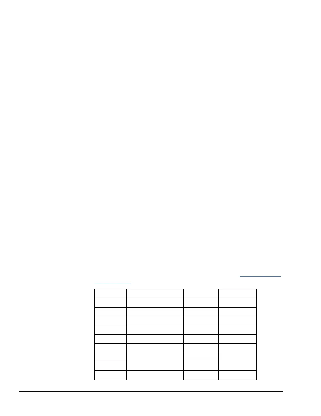
14.6.4.1 Reference Array Initialization using %M00006
For details on the contents of the reference array, refer to the section, Reference Array for
the PID Function earlier in this chapter.
Word Function Address Value
3
Sample Period
%R102 10
4 + Dead Band %R103 5
5 - Dead Band %R104 5
6
Kp
%R105 400
7 Kd %R106 0
8 Ki %R107 1500
9 CV Bias %R108 0
10
CV Upper Clamp
%R109 2000
11
CV Lower Clamp
%R110 400
290 GFK-1503E VersaMax PLC User Manual
For public disclosure