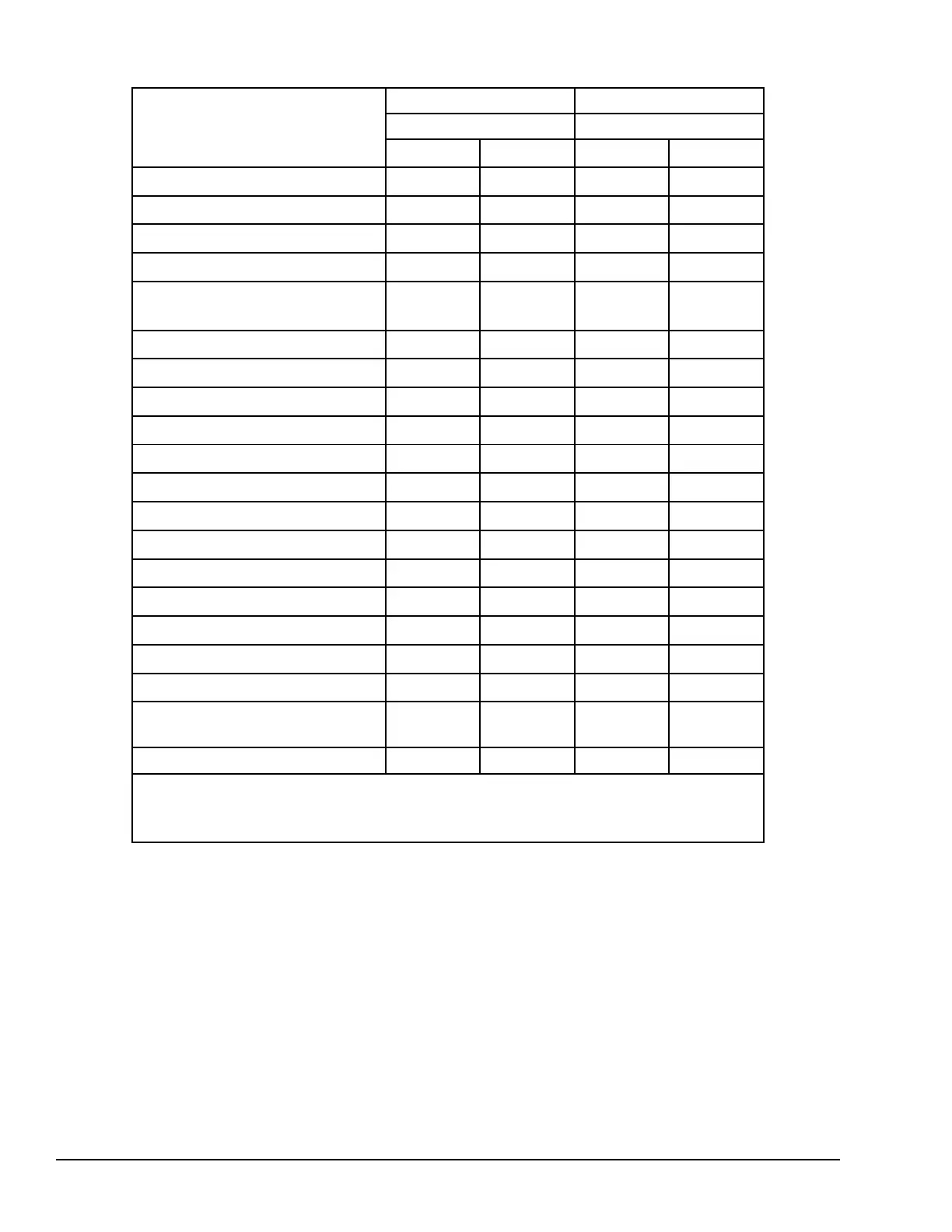
Modules Located in Main PLC Rack
Module Type
CPU005/CPUE05 CPU001/CPU002
Main Rack Main Rack
Input Output Input Output
Discrete Input Type 1
†
95
—
158
—
Discrete Input Type 2
†
117
—
189
—
Discrete Output Type 1
†
—
84
—
132
Discrete Output Type 2
†
—
101
—
152
Discrete Output w/ ESCP Per Point
Fault Reporting
—
116
—
190
Intelligent Discrete Input 20 Points
349
—
389
—
Intelligent Discrete Output 12 Points
—
294
—
369
Analog Input 4 Channels
160
—
190
—
Analog Input 8 Channels
239
—
312
—
Analog Input 15 Channels
377
—
526
—
Analog Output 2 Channels
—
109
—
161
Analog Output 4 Channels
—
145
—
202
Analog Output 8 Channels
—
217
—
285
Analog Output 12 Channels
—
289
—
367
Intelligent Analog Input 4 Channels
237
—
281
—
Intelligent Analog Input 7 Channels
261
—
305
—
Intelligent Analog Input 8 Channels
272
—
313
—
Intelligent Analog Output 4 Channels
—
212
—
264
PLC Network Comm Profibus-DP
Slave
†† †† †† ††
DeviceNet Network Master/Slave
†† †† †† ††
†
Mixed modules have both and input and output scan time values.
††
Network Communications Modules (NCM) Scan Impact Times vary depending upon the network
configuration.
310 GFK-1503E VersaMax PLC User Manual
For public disclosure



 To Next Page