4.5 Installing Additional Modules
A CPU or Expansion Receiver Module can serve up to 8 additional I/O and option
modules on the same section of DIN rail. Power must be off before adding a carrier to the
rack.
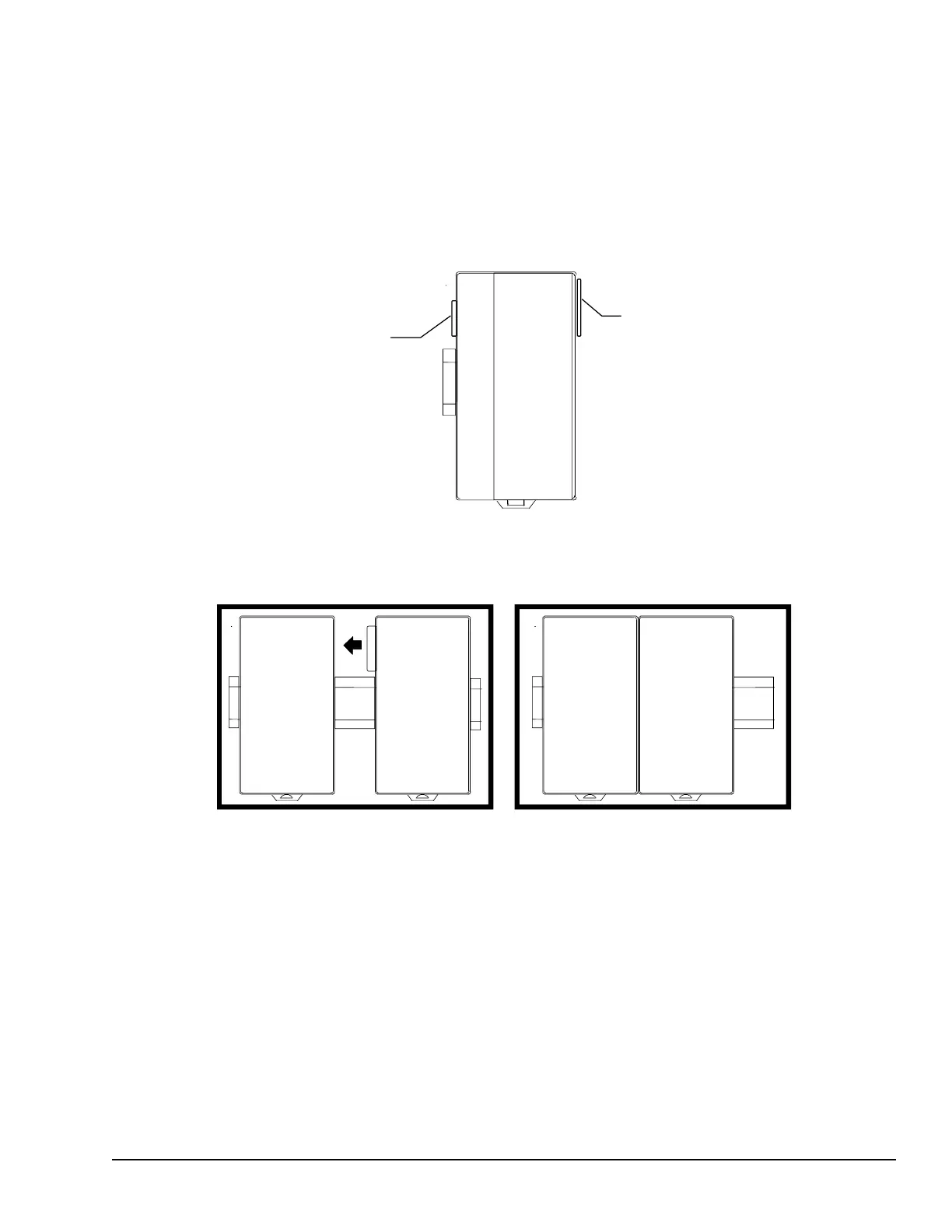
Before joining carriers to the CPU or ERM, remove the connector cover on the righthand
side of the CPU/ERM. Do not discard this cover; you will need to install it on the last
carrier. It protects the connector pins from damage and ESD during handling and use.
Do not remove the connector cover on the lefthand side.
Install each carrier close to the previously-installed carrier, then slide the properly-aligned
carriers together to join the mating connectors. To avoid damaging the connector pins, do
not force or slam carriers together.
DIN-rail clamps (available as part number IC200ACC313) should be installed at both
ends of the station to lock the modules in position.
Installation GFK-1503E User Manual 59
For public disclosure