After successful power-up, the STAT LED turns ON on the Ethernet side. Then the
STAT LED should be green for a brief moment. The LAN LED turns ON when it is
connected to the network and blinks when there is traffic. The LAN LED remains
OFF if the module is not connected to the network.
3. If the STAT LED is amber, check the PLC Fault Table. With the Station Manager
feature, you can also use the LOG command as explained in the VersaMax PLC
Ethernet Station Manager Manual ( GFK-1876).
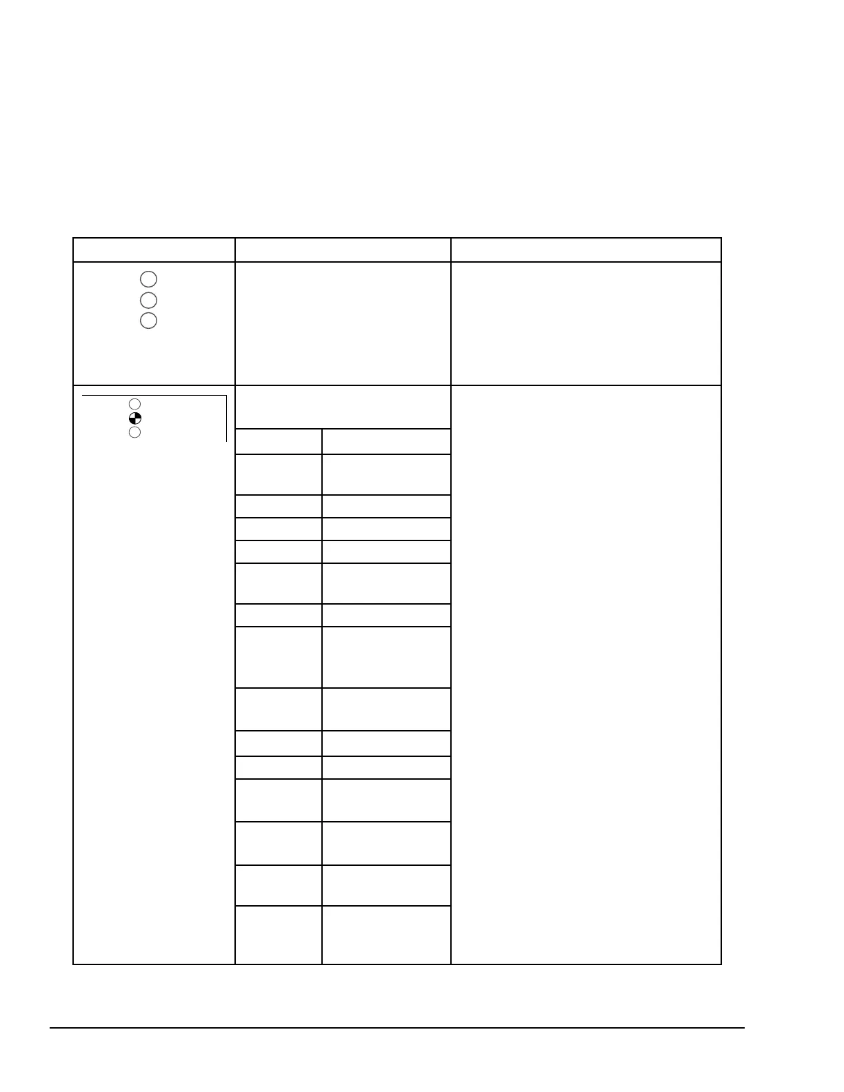
If a problem occurs during power-up, the Ethernet interface may not begin operating.
Check the Ethernet LEDs, as explained on the following table.
Ethernet LEDs Indications Actions
Off
▪ Make sure the PLC has power
▪ Look in the PLC Fault Table for problems
▪ Recheck configuration
▪ Check module installation
▪ If the problem persists, replace PLC CPU
Hardware failure mode. STAT: Blinks
2-digit error code:
▪ Note error code
1 – 2
unexpected interrupt ▪ Power cycle or restart Ethernet interface
1 – 3 timer failure
▪ If problem persists, replace the PLC
hardware.
1 – 4 DMA failure
2 – 1 RAM failure
2 – 2 stack error
2 – 3
shared memory
interface error
2 – 4 firmware CRC error
1-Mar
unidentified
instruction, or divide
by 0
3 – 2
unexpected SWI
interrupt
3 – 3
prefetch abort error
4-Mar data abort error
3 – 5
unexpected IRQ
request
3 – 6
unexpected FIQ
interrupt
7-Mar
reserved exception
error
1-Apr
fatal operating
system startup or
EEPROM error
262 GFK-1503E VersaMax PLC User Manual
For public disclosure